
Re-Wire Control Panel?
- Thread starter Inception85
- Start date
You are using an out of date browser. It may not display this or other websites correctly.
You should upgrade or use an alternative browser.
You should upgrade or use an alternative browser.
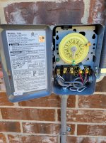
The white wires on terminal A are for the clock. With that said it looks like you are are using 240v, I would have went with the t104. But you should be able to move one of the clock wires to terminal 1, and run your neutral to terminal A where you have the other clock wire. The diagram says the clock is 120v. But you should double check with Allen because I don’t know if that’s up to code. @ajw22
Mechanicman
Gold Supporter
- Apr 18, 2021
- 56
- Pool Size
- 25000
- Surface
- Plaster
- Chlorine
- Salt Water Generator
- SWG Type
- Pentair Intellichlor IC-60
You should be able to replace just the clock motor without having to replace the whole timer. Get the number off of the old one and look for a replacement.
Thank you.The white wires on terminal A are for the clock. With that said it looks like you are are using 240v, I would have went with the t104. But you should be able to move one of the clock wires to terminal 1, and run your neutral to terminal A where you have the other clock wire. The diagram says the clock is 120v. But you should double check with Allen because I don’t know if that’s up to code. @ajw22
- Jul 21, 2013
- 65,736
- Pool Size
- 35000
- Surface
- Plaster
- Chlorine
- Salt Water Generator
- SWG Type
- Pentair Intellichlor IC-60
The T103 has a 120V motor that sues one of the hot lines and a neutral line.
I can't tell if a neutral line was run into the box from the CB along with the two 240V hots.
If you have a neutral, and I see a white wire on the bottom of the box, then the neutral wire from the CB goes to the left most screw and one of the think whit wires moved to under screw 1 to power the clock.
If you don't have a neutral then youc an pull one into the box, chnage the motor to 240V or change the timer mechanisim to a T104M that has a 240V clock motor.
If the black wires are Line and the red wires are Load, then it appears wires 2 & 3 should be swapped.
First, what time clock did you purchase? T103, T104? Right now you have both motor wires on the same terminal. That means that no power is going to the motor. If it is a T104, one white goes to each of the line terminals (1 and 3) and there should be 240v going to the clock. (Measure with probes on 1 and 3.)
If that is a T103, you need to take one white wire off of the A terminal and place it on 1 or 3 (line voltage) and take the neutral wire and attach it to the A terminal. That way you will have power to the clock motor. If you have a ground-fault circuit breaker in the system for the pump, it will trip if wired this way on a T103.
If that is a T103, you need to take one white wire off of the A terminal and place it on 1 or 3 (line voltage) and take the neutral wire and attach it to the A terminal. That way you will have power to the clock motor. If you have a ground-fault circuit breaker in the system for the pump, it will trip if wired this way on a T103.

- Feb 6, 2015
- 7,855
- Pool Size
- 12300
- Surface
- Plaster
- Chlorine
- Salt Water Generator
- SWG Type
- CircuPool RJ-45 Plus
First determine what wires come out of each conduit - and where the other end of that conduit terminates.
Then see if a white neutral wire comes into the timer from the conduit that runs back to the circuit breaker.
Report back here and someone will help determine what needs to be done to get it working.
Don't be swapping wires around without knowing where they come from.
Then see if a white neutral wire comes into the timer from the conduit that runs back to the circuit breaker.
Report back here and someone will help determine what needs to be done to get it working.
Don't be swapping wires around without knowing where they come from.
Last edited:
Thread Status
Hello , This thread has been inactive for over 60 days. New postings here are unlikely to be seen or responded to by other members. For better visibility, consider Starting A New Thread.