We just had an electrician remove an old timer from our system. It was unnecessary as we now have variable speed pumps. He said that all he did was remove the timer and connect the wires the same way as he found them. However, the Raypak made sparking sound and something smelt like it was burning. Now it powers on OK but it reads PV output fault. Not sure where to begin troubleshooting this. Thanks much in advance.

Raypak 406A
- Thread starter drpobgyn
- Start date
You are using an out of date browser. It may not display this or other websites correctly.
You should upgrade or use an alternative browser.
You should upgrade or use an alternative browser.
You may need to do a hard reset. I would turn the desired temp so there is no call for heat. Turn your multimeter to vac and check between mv/pv and pv on the automatic gas valve. You should have 0 but if you have anything one of the relays on the board is stuck which is causing the pv fault. It’s sensing voltage in an uncommanded state. Normal operation check temp check cfh check switches spark send pv output check flame (7-10seconds) send mv output. The board is sensing faulty readings or creating it.
You may need to do a hard reset. I would turn the desired temp so there is no call for heat. Turn your multimeter to vac and check between mv/pv and pv on the automatic gas valve. You should have 0 but if you have anything one of the relays on the board is stuck which is causing the pv fault. It’s sensing voltage in an uncommanded state. Normal operation check temp check cfh check switches spark send pv output check flame (7-10seconds) send mv output. The board is sensing faulty readings or
Is that something that I can learn in the manual? I have a multi meter though
The manual is pretty vague on this. Basically after the sequence above it will send 24vac to open the solenoid for the pilot on the auto gas valve. Your heater board is sensing volts pre ignition phase.
Pv “pilot valve” mv/pv “common” you should get 24vac during ignition phase not before.
Pv “pilot valve” mv/pv “common” you should get 24vac during ignition phase not before.
With the risk of sounding like a complete fool... Where are these terminals labeled? Its not clear anywhere on my unit. Also in full disclosure... the electrician thought the problem might be witht he 2 blue wires. Currently they are not connected to anything.
This is a judge free zone. They would be directly on the gas valve.

Can you post the pic of the blue wires? To and from they come?
Can you post the pic of the blue wires? To and from they come?
Last edited:
- Jul 21, 2013
- 65,224
- Pool Size
- 35000
- Surface
- Plaster
- Chlorine
- Salt Water Generator
- SWG Type
- Pentair Intellichlor IC-60
the electrician thought the problem might be witht he 2 blue wires. Currently they are not connected to anything.
Post some pics of what you are looking at and your wiring.
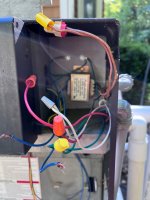
Thank you... Am sending pics. I couldnt last night as it was too late. When I turned on the heater this morning, I heard the sparking bad sound (Not the normal ignition sound). I determined that it happened when the bottom pole (purple) was attached to the pilot terminals. If that helps.This is a judge free zone. They would be directly on the gas valve.
View attachment 419782
Can you post the pic of the blue wires? To and from they come?
The electrician said that initially the blue wires were attached to the brown wires which are both "hot". Right now they are all separated.
Attachments

Can you show us where the blue wires go? The board for the heater drops down when you unscrew the four screws on each side with that front panel off. Can you also show us where those flex conduits go coming out of the heater so we have a better idea of the history. Is the buzzing coming from the gas valve or the igniter. The igniter would be buzz…buzz…buzz. Gas valve can sound like this
Thats definitely the sound. The Gas Solenoid sound. The Blue wires Dip down underneath and I will get a picture when I am home later. Essentially the 2 Brown wires (which were each connected to a blue) came in from an old pool timer that was not being used as a timer anymore. But there were several electrical connections there and the electrician supposedly wired them up properly. When we tried to turn the heater on after he finished, we heard the gas solenoid sound but also something was burning inside... like a component, not the burner.
- Jul 21, 2013
- 65,224
- Pool Size
- 35000
- Surface
- Plaster
- Chlorine
- Salt Water Generator
- SWG Type
- Pentair Intellichlor IC-60
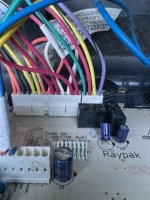
I can't follow all the wires in the pic and what wires are capped.
Check that the heater is properly wired for 120V or 240V, whichever is being used.
See page 23 in https://s3.amazonaws.com/AWSProd/sites/raypakcom/documents/241236.pdf

Check that the heater is properly wired for 120V or 240V, whichever is being used.
See page 23 in https://s3.amazonaws.com/AWSProd/sites/raypakcom/documents/241236.pdf

We did confirm that it is wired for 120 as in the photo... but I will certainly check again. And I will get a better picture.I can't follow all the wires in the pic and what wires are capped.
Check that the heater is properly wired for 120V or 240V, whichever is being used.
See page 23 in https://s3.amazonaws.com/AWSProd/sites/raypakcom/documents/241236.pdf
View attachment 419919
OK... Thanks for all your patience. The help is much appreciated.We did confirm that it is wired for 120 as in the photo... but I will certainly check again. And I will get a better picture.
I just confirmed voltages and the wires are correct for 120V. The red wire from Transformer is capped. Green goes to ground. White Neutral. Black is 120V. The 2 Brown wires coming in are each 120V but not attached to anything. The Blue wires just jump the purple connection at the pilot assembly (The bottom terminal. So if they were connected together, the purple wire would go directly from the pilot terminal to the electronics board. Its like a switch should be there. The electrician said that each end of blue was attached to 120V but that makes no sense.
You are right that doesn’t make sense. Maybe at one time the brown were used to close a dry relay, or to power the heater 240v. Can you send picture of the board and the blue wires where they connect specifically. They probably were used to turn off and on the heater by interrupting pilot. This should only be done using the fireman switch. I would feel more comfortable telling you to connect blue wires after I see pictures. But that is most likely pv output problem.
Going to get a pic now. But basically, someone cut the purple wire. To each end they attached a blue wire. If I connect the Blues, it completes the circuit on the purple. Should I connect the blues and reset? I think I see the reset button on the electronics board.You are right that doesn’t make sense. Maybe at one time the brown were used to close a dry relay, or to power the heater 240v. Can you send picture of the board and the blue wires where they connect specifically. They probably were used to turn off and on the heater by interrupting pilot. This should only be done using the fireman switch. I would feel more comfortable telling you to connect blue wires after I see pictures. But that is most likely pv output problem.


That heater should not be put in service with a main gas valve that corroded.Thank you... Am sending pics. I couldnt last night as it was too late. When I turned on the heater this morning, I heard the sparking bad sound (Not the normal ignition sound). I determined that it happened when the bottom pole (purple) was attached to the pilot terminals. If that helps.
The electrician said that initially the blue wires were attached to the brown wires which are both "hot". Right now they are all separated.
Yes, connect blue wires or remove blue wires and connect purples together. Shut power down for 90 seconds and restart. Make sure to practice cool down periods when shutting of heater. When you turn heater off let pump run for a few minutes so you don’t have boiling water sitting in exchanger.
Ok. Done and reset. Not calling for heat. Get PV output failure
Across red and yellow is 29v ac
Across purple and yellow 29v ac
Across red and purple is 0
Across red and yellow is 29v ac
Across purple and yellow 29v ac
Across red and purple is 0

Thread Status
Hello , This thread has been inactive for over 60 days. New postings here are unlikely to be seen or responded to by other members. For better visibility, consider Starting A New Thread.