I ordered the RJ-45 when I spoke to the DSP rep he preferred the Rj over the core series due to the screen info. He also indicated that for lower speed water flow mounting vertically would be recommended or as an alternative mounting the cell upside down for lower water flow which he said you would see on the display screen if there is a low flow condition.

Pool Perfect+ Phos Free with SWG and other SWG questions?
- Thread starter Quinten
- Start date
You are using an out of date browser. It may not display this or other websites correctly.
You should upgrade or use an alternative browser.
You should upgrade or use an alternative browser.
There are few ways your pump could have been connected to constant power. Try to trace those line back from the pump. We should be able to assist in getting the SWG connected to the timer.
I recently installed the RJ-45+. Too soon to comment on longevity, but I chose it based on reviews and info here. No complaints so far. If you buy from Discount Salt Pool, make sure you take advantage of the $10 upgrade promotion. No hurry, I don't think it ever ends.
Getting ready to wire the Circupool RJ45+ SWG to the timer. The CS Pump installer by passed the timer so it's currently not in use, although I seemed to have misplaced the on/off cogs for the timer

I did check the circuit breaker function and if either of the smaller switches at each end are turned off, the pump also turns off. The label on the cover indicates the left most switch is for the pool light and the GFI receptacle, but also is turning off the pump???
The two black wires with the wire nuts are going to a x10 switch for the pool light but I will be replacing that with an RF switch as the x10 remote is quite temperamental.
Attachments


- Apr 10, 2018
- 6,545
- Pool Size
- 18375
- Surface
- Plaster
- Chlorine
- Salt Water Generator
- SWG Type
- CircuPool RJ-45 Plus
Maybe @ajw22 can take a look at the wiring. If your pump is connected to timer terminals 1 and 3, you would connect the SWG to terminals 2 and 4 for 240 volts.
- Jul 21, 2013
- 66,499
- Pool Size
- 35000
- Surface
- Plaster
- Chlorine
- Salt Water Generator
- SWG Type
- Pentair Intellichlor IC-60
What smaller switches at each end are you talking about? I am lost.
It looks to me like everything is wired to the line screws 1 & 3 for continuous power.
If you want to get the Intermatic switch to control the SWG then connect it to screws 2 & 4.
And you should really have a 20amp GFCI CB for your pool pump.
I would question how much load you have on the one 20 Amp circuit. A circuit should not be loaded at more then 80% of capacity which is 16 amps for a 20 amp CB.
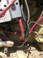
The pump is connected to the circuit breaker (purple marks on the red and black wires). The solar controller is connected to lines 1 & 3 under the clock (pink marks) along with the clock power.
The two small switches I was referring to are marked with green
Nothing is connected to the timer switched terminals which I will test but should be 2 & 4 (yellow marks) and that is where I would connect the SWG.
Pool pump running at 2800 rpm's shows 1525 watts, not sure what the amp draw is.
The two small switches I was referring to are marked with green
Nothing is connected to the timer switched terminals which I will test but should be 2 & 4 (yellow marks) and that is where I would connect the SWG.
Pool pump running at 2800 rpm's shows 1525 watts, not sure what the amp draw is.
Attachments

- Jul 21, 2013
- 66,499
- Pool Size
- 35000
- Surface
- Plaster
- Chlorine
- Salt Water Generator
- SWG Type
- Pentair Intellichlor IC-60
Those two small switches are your 120 volt Circuit Breakers. CBs should really not be used as switches. Constant toggling of them will wear them out.
You have to determine circuit amperage by the maximum amps on the pump motor plate, not by some lower speed you may run it at. You need to ensure that the circuit is safe if the pump is run at maximum speed.
You have to determine circuit amperage by the maximum amps on the pump motor plate, not by some lower speed you may run it at. You need to ensure that the circuit is safe if the pump is run at maximum speed.
The Pentair Intelliflo VS pump full load is 16 amps. I don't really use the CB switches, I was toggling them today when I was checking the wiring, outside of that probably not touched in a few years. I assume the reason the pump shut off (although it is labeled pool light/gfe outlet) when I toggled the left 120 volt breaker is the way the Pentair replacement pump was wired versus the old pump that was on the timer. The red wire to the pump is on the left terminal which is on the 120v CB and the pump black wire is on the right terminal which is on the other 120v CB. The two black wires from the 240v CB go to the timer.Those two small switches are your 120 volt Circuit Breakers. CBs should really not be used as switches. Constant toggling of them will wear them out.
You have to determine circuit amperage by the maximum amps on the pump motor plate, not by some lower speed you may run it at. You need to ensure that the circuit is safe if the pump is run at maximum speed.
Should the pump be wired to the 240v CB? I did clean up the wiring (cut ends and re-stripped) on the CB as there were strands hanging and removed the x10 switch and wired in a RF remote for the pool light using the neutral and load from the GFI.
As far as the SWG, the wiring references ground and also that it must be properly grounded and bonded.
I have located the bare copper ground wire from the pump... that would be the bonding ground to use with the bonding lug on the SWG controller? The green ground wire on the SWG power cord would go to the grounding block at the bottom of the wiring box where the green wire from the house wiring is attached? The other two lines on the SWG power cord would go to terminals 2 & 4 on the timer.
Should there be a location where the bonding wire should be attached? I try and trace the bare wire and see where it goes.
Thanks...
Attachments


- Jul 21, 2013
- 66,499
- Pool Size
- 35000
- Surface
- Plaster
- Chlorine
- Salt Water Generator
- SWG Type
- Pentair Intellichlor IC-60
The red wire to the pump is on the left terminal which is on the 120v CB and the pump black wire is on the right terminal which is on the other 120v CB.
So the pump and the timer are on two separate circuits.
Except that your CB setup for your pump is not to code and borderline dangerous.
Both CBs must be tied together, like the middle two CBs are, so that when one leg trip the CB, both CBs trip and you don't have either hot wire energized. It is a safety hazard to have it set the way you do. Someone can trip one side of the breaker, see the pump is off, and start working on the pump while the other side is HOT!
In additon you should have a 240V 20 amp GFCI CB for the pump.
The two black wires from the 240v CB go to the timer.
And that powers the Solar controller and will power the SWG. Anything else?
Should the pump be wired to the 240v CB?
The proper fix is:
- Replace the center CB with a 240V GFCI CB made specifically for VS pumps like the Siemans QF220AP or the Pentair PA220GF
- Connect the IntelliFlo pump to the 240V CB
- Change your Solar Controller and SWG to 120V
- Use one of your outside CBs for a 120V circuit to the timer
- You need to chnage the T104 timer with a 240V clock to a T101M timer mechanism with a 120V clock
- Rewire the timer for 120V and connect the Solar Controller and SWG through the timer with 120V
Electrical GFCI - Further Reading
 www.troublefreepool.com
I did clean up the wiring (cut ends and re-stripped) on the CB as there were strands hanging and removed the x10 switch and wired in a RF remote for the pool light using the neutral and load from the GFI.
You have those outside CBs providing 240V to the pump and 120V to the lights and solar controller. No wonder things were confusing.
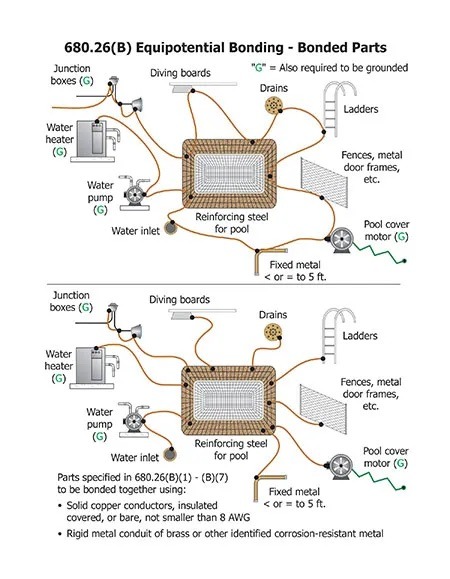
As far as the SWG, the wiring references ground and also that it must be properly grounded and bonded.
Ground and bonding are two separate things.

Bonding vs Grounding
Electricity and water don't mix. Learn a few basic tips how to keep your family safe when dealing with electricity around your pool.
www.troublefreepool.com
I have located the bare copper ground wire from the pump... that would be the bonding ground to use with the bonding lug on the SWG controller?
It is the bonding wire, not the bonding ground, and you extend it with copper lugs and split bolts to connect to the SWG bond lug.
Electrical Bonding - Further Reading
www.troublefreepool.com
The green ground wire on the SWG power cord would go to the grounding block at the bottom of the wiring box where the green wire from the house wiring is attached?
Yes,
The other two lines on the SWG power cord would go to terminals 2 & 4 on the timer.
Well of you follow the recommendation above you will rewire the timer for 120V and only the hot wire connects through the timer.
Should there be a location where the bonding wire should be attached?
The bonding wire runs from the SWG bonding lug to connect to the bonding wire connected to the pump using copper split bolts.
Ok, thanks for the info... I will look into the bonding and grounding more thoroughly. I know the bare wire enters the circuit breaker/timer box but didn't notice where it went. I'll go over the links provided and see what I find out. I know the bare wire goes to the pump, then exits the pump and goes into the ground. Would that be a grounding rod or???
I'm not sure about how to change the solar controller to 120v, I'll open it up and see what the model is and what may be needed to change it to 120v.
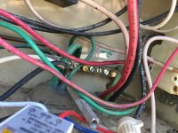
On the 240v GFI CB, does the white neutral wire connect to the bus bar where the house neutral wire is connected (green circle in photo) or is that connected directly to the house neutral wire bypassing the bus bar?
I know I'll have more questions but very glad you are providing this info as it's been quite helpful!
I'm not sure about how to change the solar controller to 120v, I'll open it up and see what the model is and what may be needed to change it to 120v.
On the 240v GFI CB, does the white neutral wire connect to the bus bar where the house neutral wire is connected (green circle in photo) or is that connected directly to the house neutral wire bypassing the bus bar?
I know I'll have more questions but very glad you are providing this info as it's been quite helpful!
Attachments

Last edited:
- Jul 21, 2013
- 66,499
- Pool Size
- 35000
- Surface
- Plaster
- Chlorine
- Salt Water Generator
- SWG Type
- Pentair Intellichlor IC-60
Ok, thanks for the info... I will look into the bonding and grounding more thoroughly. I know the bare wire enters the circuit breaker/timer box but didn't notice where it went. I'll go over the links provided and see what I find out. I know the bare wire goes to the pump, then exits the pump and goes into the ground. Would that be a grounding rod or???
The wire probably goes from the pump to the pool and deck.
The bonding wire should never be connected to the electrical panel or to a ground rod.
I'm not sure about how to change the solar controller to 120v, I'll open it up and see what the model is and what may be needed to change it to 120v.
What model solar controller?
I did look at some of the 240v CB, some have a white wire extending from them... where does that connect to?
The pigtail white wire on GFCI CBs connect to the neutral bar in the panel.
Here is the info on the solar controller, I see that I can change it over to 120v, since the timer is approaching 25 years old, I can get a new timer, but read that they are failing after a few years... quality of new timers not good?
Would adding a 240v GFI CB for the pool pump and a regular 240v CB for the timer/SWG and Solar controller be a valid option or should they be converted down to 120v? I'll need to take a closer look as to where the load wire for the 120v GFI and pool light is coming from.
Good news is the new remote pool light works well!
I thought all the difficult work would be plumbing in the SWG cell!
I'll look into this in more detail Monday!
Thanks again Allen!!! Have a Happy Easter!
Attachments

I was looking for the Siemens QF220AP but seem to only be finding the QF220A, the only AP I found was the 30 amp QF230AP. What is the P designation (pool)?
I do have another question. Having difficulty locating a Siemens QF220AP, but did find a 30 amp QF230AP. I checked the house breaker and the pool circuit there is 30 amp. I can't tell the wire size at the pool end, but it looks to be 10 gauge, here are some pictures of the house CB and the pool box wiring if you can tell from the markings what size the wire is and if using the 30 amp QF230AP breaker would be good? It's also about $40 less than the 20 amp and is a "AP" rather than an "A"
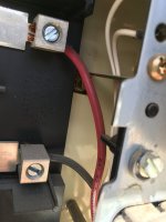
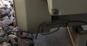
Now regarding the bonding wire, I followed it out of the ground near the pump pad, then connects to the pump bonding lug, then another wire wraps around (not really connected well it appears) and continues up to the breaker box and is connected to the grounding bus (pics B1 & B2).
This has certainly been an adventure so far!
Attachments


- Jul 21, 2013
- 66,499
- Pool Size
- 35000
- Surface
- Plaster
- Chlorine
- Salt Water Generator
- SWG Type
- Pentair Intellichlor IC-60
I do have another question. Having difficulty locating a Siemens QF220AP, but did find a 30 amp QF230AP. I checked the house breaker and the pool circuit there is 30 amp. I can't tell the wire size at the pool end, but it looks to be 10 gauge, here are some pictures of the house CB and the pool box wiring if you can tell from the markings what size the wire is and if using the 30 amp QF230AP breaker would be good? It's also about $40 less than the 20 amp and is a "AP" rather than an "A"
I can't tell from the pic the wire size. The red wire has lettering but the pic does not show all the lettering on the red wire. Take a closer look at what is printed on the red jacket.
You can replace the subpanel feed breaker in the house with the GFCI CB. The issue that you may have is that CB will trip if the combined loss from all the devices are greater then 6 mA. Each device alone can have some current loss that does not cause a trip. But when added together it becomes too much. We are seeing this problem in this thread...
GFCI outlet for pool lights keeps tripping
As soon as the pool/spa lights are turned on the GFCI breaker trips. I think I have checked everything possible and am now stumped. The hot wire reads 120v with a multimeter. Test #1: 1. Unhook the two wires from the output of the relay. These two wires go to the spa and pool lights. 2. Turn...
www.troublefreepool.com
So having the GCFI on individual circuits prevents false trips that may occuir when put on a feeder circuit.
Now regarding the bonding wire, I followed it out of the ground near the pump pad, then connects to the pump bonding lug, then another wire wraps around (not really connected well it appears) and continues up to the breaker box and is connected to the grounding bus (pics B1 & B2).
Connecting a bonding wire to the ground bus is incorrect. I would disconnect that and remove the bond wire from the box. Many electricians who are not familiar with pools do not understand the difference between boning and grounding.
Last edited:
Ok, thanks... I'll see if I can get a better shot of the wire coming into the box and remove the bonding wire from the ground block. Not sure when that was done but either when the pool was built or the pump replaced which I'm guessing the later as that is how the pump got wired to the existing separate outside CB
Well after several attempts I finally got a decent shot that shows it is 10 awg wire.
So my question is whether it would be better to have a QF230AP or QF220A given the 10 awg wire and the 30amp house breaker? The 30amp AP breaker costs ~ $40 less, I just can't find out what the "P" designation means and no luck finding a QF220AP.
Thanks again!
Attachments
- Jul 21, 2013
- 66,499
- Pool Size
- 35000
- Surface
- Plaster
- Chlorine
- Salt Water Generator
- SWG Type
- Pentair Intellichlor IC-60
This is available...
Amazon.com: Pentair PA220GF 2-Pole GFCI Circuit Breakers, 20-Ampere : Patio, Lawn & Garden
Amazon.com: Pentair PA220GF 2-Pole GFCI Circuit Breakers, 20-Ampere : Patio, Lawn & Garden
www.amazon.com
Well for $100 less wouldn't this work since there is10 awg wire and a 30amp house breaker? I did find a 20amp at Home Depot but no "AP" designation. It shows class A on the label, is that what the "A" stands for? Just don't see any reason to spend that much for the pentair which seems to just be a rebranded Siemens.
Siemens QF230AP
Siemens 20 Amp Double Pole Type QPF2 GFCI
Siemens QF230AP
Siemens 20 Amp Double Pole Type QPF2 GFCI
- Jul 21, 2013
- 66,499
- Pool Size
- 35000
- Surface
- Plaster
- Chlorine
- Salt Water Generator
- SWG Type
- Pentair Intellichlor IC-60
Well for $100 less wouldn't this work since there is10 awg wire and a 30amp house breaker? I did find a 20amp at Home Depot but no "AP" designation. It shows class A on the label, is that what the "A" stands for? Just don't see any reason to spend that much for the pentair which seems to just be a rebranded Siemens.
Siemens QF230AP
Siemens 20 Amp Double Pole Type QPF2 GFCI
I described why in post #34.
I am trying to save you from unnecessary GFCI trips. With the 30 amp breaker if you get a GFCI trip it will be difficult to diagnose which device is causing it.
I think not getting GFCI trips is worth more then $20.
I was going to put the GFCI in the pool breaker box running just the pump, then add a second 20 amp 240v CB for the solar controller and the clock running the SWG off the clock at 240v. I really don't want to take the solar controller apart to change to 120v since with my luck, things will break off the circuit board since it's 20 years old, I can use the existing T104 clock. I was going to add one 120v breaker for the 120v GFCI outlet on the side panel that also runs the pool light. That will give be individual breakers for the pump, the solar controller/clock/SWG and the pool light GFCI outlet.
The qf230ap shows a
Let me know if I'm off base here...
The qf230ap shows a
- 10kA interrupting rating
Let me know if I'm off base here...
- Jul 21, 2013
- 66,499
- Pool Size
- 35000
- Surface
- Plaster
- Chlorine
- Salt Water Generator
- SWG Type
- Pentair Intellichlor IC-60
Are the wires running from the CB to the pump #10 AWG? You can only put a 30 amp breaker if the wire to the pump is #10.
I thought we were talking that the #10 wire is between the house panel and the pool panel.
It looks to me like the pool breaker panel can only fit two normal 240Volt breakers. Youd on;t have room for two 240V breakers and a 120 volt breakers. Unless you use a split combo breaker like what you have now that is 120V on the outside and 240V on the inside.
Thread Status
Hello , This thread has been inactive for over 60 days. New postings here are unlikely to be seen or responded to by other members. For better visibility, consider Starting A New Thread.