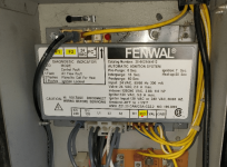
Pentair Mastertemp 400 - Not igniting No errors

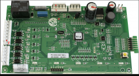
Ok, your board is R13 Rev D and a newer board is R14 Rev L.
 
I think that the AFS error is the reason that the heater is not coming on.

The blower might be bad or the Fenwal might be bad.

I think that the circuit board is also bad, which is why you are not getting any error lights.

Possibly freeze damage caused water to fill the combustion chamber and get into the blower.
 
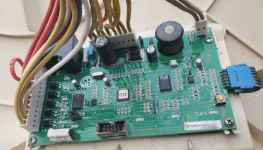
I checked board again this afternoon. this is no water on the board, but there are what I would call blisters on the back of several of the components probably due to the freeze. The heater is outside and I did not winterize it before temps got down in the teens for a couple of days. That was back in Feb 2020, but I guess I could be just now feeling the effects. I pulled the two bottom bolts, no water came out.

I guess my question at this point is where to start replacing parts...should I start with the control board since it shows obvious signs of age/damage?
 

Attachments

  • 20211017_175740.jpg
    20211017_175740.jpg
    244 KB · Views: 8
  • 20211017_180116.jpg
    20211017_180116.jpg
    331.3 KB · Views: 8
  • 20211017_180205.jpg
    20211017_180205.jpg
    344.6 KB · Views: 7
I think that the AFS error is the reason that the heater is not coming on.

The blower might be bad or the Fenwal might be bad.

I think that the circuit board is also bad, which is why you are not getting any error lights.

Possibly freeze damage caused water to fill the combustion chamber and get into the blower.
The blower is working when I direct wire it to the ICM.
 
Can you show the sticker with the barcode and the date?

Picture3_59.png
 

Attachments

  • 20211017_180205.jpg
    20211017_180205.jpg
    344.6 KB · Views: 6
I think that the circuit board is likely to be bad.

The Fenwal might also be bad.

Multiple issues are more difficult to diagnose and the parts are not cheap.

I would probably start with the circuit board, but be ready to replace the Fenwal as well.

This is a bad situation where you might spend a lot of money and regret not just replacing the heater if the two parts don't fix the problem.
 
This might help you troubleshoot your problem https://www.kidde-fenwal.com/Media/Data Sheets/series-35-66_24-VAC-hot-surface-ignition-control-F-35-66.pdf The blower motor is powered/started by the Fenwal. If you look at the wiring diagrams there are some discrepancies in terminal labeling. TH on your Fenwal is the same as W in the listed wiring diagram. 24VAC on your Fenwal is the same as R in the listed wiring diagram. The fenwal is powered to "standby" by having 24V between GND and 24VAC. The ignition sequence is started by having 24V between GND and TH. When the ignition sequence is started the Fenwal first checks to make sure that the air pressure switch is "open" and not stuck in the closed position without the blower running. If the air pressure switch is open, it will then power the blower motor by closing a relay for one leg of the blower motor through the NO (normally open) contacts at F1/F2. Do you have 24V between GND and 24VAC at the Fenwal? Do you have 24V between GND and TH when you are asking the heater to start? If your ground is good, you could try jumping the "hot" (ungrounded) leg of the 24V from the transformer to TH on the Fenwal to see if the ignition sequence will start. Will try to answer any questions you may have if you feel comfortable/safe troubleshooting the electrical with a multimeter.
 

Enjoying this content?

Support TFP with a donation.

Give Support
This might help you troubleshoot your problem https://www.kidde-fenwal.com/Media/Data Sheets/series-35-66_24-VAC-hot-surface-ignition-control-F-35-66.pdf The blower motor is powered/started by the Fenwal. If you look at the wiring diagrams there are some discrepancies in terminal labeling. TH on your Fenwal is the same as W in the listed wiring diagram. 24VAC on your Fenwal is the same as R in the listed wiring diagram. The fenwal is powered to "standby" by having 24V between GND and 24VAC. The ignition sequence is started by having 24V between GND and TH. When the ignition sequence is started the Fenwal first checks to make sure that the air pressure switch is "open" and not stuck in the closed position without the blower running. If the air pressure switch is open, it will then power the blower motor by closing a relay for one leg of the blower motor through the NO (normally open) contacts at F1/F2. Do you have 24V between GND and 24VAC at the Fenwal? Do you have 24V between GND and TH when you are asking the heater to start? If your ground is good, you could try jumping the "hot" (ungrounded) leg of the 24V from the transformer to TH on the Fenwal to see if the ignition sequence will start. Will try to answer any questions you may have if you feel comfortable/safe troubleshooting the electrical with a multimeter.
Thanks for the info and document. I tested GND to 24VAC and I am not getting any volts. Does that point to a bad transformer? Definitely not an electrician but willing to try.
 
The blower is not starting up, which means that the AFS light should be coming on.

Since you are not getting an AFS light, the circuit board is probably bad.

I would start with a new board and then see what happens.
 
In this picture, the red dot is the wire going to the 24 VAC terminal of the Fenwal Ignition Control Module.

The blue dot is the wire going to the Ground terminal of the Fenwal Ignition Control Module.

Check for 24 volts between the red and blue dot wires at the holes in the connector.

1634593795053.png
 
To start the blower, the wire with the red dot sends 24 VAC to the IND (Inducer/Blower) terminal of the Fenwal Ignition Control Module.

This closes the relay between the F1 and F2 terminals on the Fenwal Ignition Control Module, which sends power to the blower.

Check for 24 VAC from the IND terminal to the Ground terminal when the blower should be on.

1634594615114.png
1634594715416.png
 
Well, like I said not an electrician...I went back and checked the GND to 24VAC and GND to TH Terminals, both came back with 33Volts....TH reading was near 10 Volts until the cycle started then ramped up to around 33 Volts.

I also checked the two board locations in the pics above, both get 24 volt reading on multimeter.

Will check the IND to GND next
 
Once the Air Flow Switch closes, the TH terminal get 24 VAC to activate the HSI (Hot Surface Ignitor).

After 20 seconds, the VAL (Gas Valve) terminal gets 24 VAC to power the gas valve.
 
Actually IND is the same as PS (in the fenwal pdf) and is the pressure switch input to the Fenwal which is checked for open (no 24V between GND and IND/PS) before starting the blower and for closed (24V between GND and IND/PS) after blower starts before powering the ignitor in the sequence. 24V between GND and TH/W is what starts the call for heat sequence.
 
After the AFS closes, 24 VAC goes from Pin 8 of the J2 connector to pin 4 of the J1 connector (Numbered right to left).

Pin 4 of J1 goes to the TH terminal on the Fenwal, which closes the relays to the ignitor.

The Val wire sends 24 VAC to pin 5 of the J1 connector, which then goes to pin 1 of the J3 connector.

Pin 1 of J3 goes to the AGS (Automatic Gas Shutoff) sensor.

The AGS is normally closed and the 24 VAC returns to pin 2 of the J3 connector.

24 VAC then goes from pin 5 of the J3 connector to the gas valve.

1634596690717.png
 

Enjoying this content?

Support TFP with a donation.

Give Support
Thread Status
Hello , This thread has been inactive for over 60 days. New postings here are unlikely to be seen or responded to by other members. For better visibility, consider Starting A New Thread.