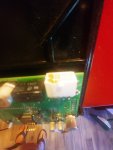
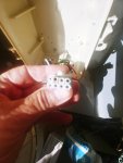
This will be the 3rd time over approx 4 years that the connector from the power supply to the IntelliPh circuit board overheats and melts. I have had this occur not only on original unit but replacement (complete new unit). I have also replaced 1 control unit separately. The overheated pin in plug occurs on the black wire only. I have a new printed circuit board avail to install, however the plug that would plug onto board is damaged and as far as I can tell Pentair nor elsewhere sells what I would call the wiring harness from the power supply. You have to buy complete controller box to get that item. Anyone experience this issue? I love my IntelliPh except for this issue.

Pentair IntelliPh Circuit?wiring supply issues
- Thread starter riverlvr
- Start date
You are using an out of date browser. It may not display this or other websites correctly.
You should upgrade or use an alternative browser.
You should upgrade or use an alternative browser.
- Jul 21, 2013
- 65,109
- Pool Size
- 35000
- Surface
- Plaster
- Chlorine
- Salt Water Generator
- SWG Type
- Pentair Intellichlor IC-60
- Nov 12, 2017
- 12,636
- Pool Size
- 12300
- Surface
- Plaster
- Chlorine
- Salt Water Generator
- SWG Type
- Pentair Intellichlor IC-40
Nothing like that here. It's been in service almost 2 years now, I think. If you eliminate the IntellipH controller from the loop, and just run the SWG off the power supply, does that overheat? That would be a troubleshooting step to see if the problem is with the IpH or the IC.
I would then try running the IpH controller and IC, with the IpH disconnected, to further eliminate the source of the problem.
You cannot run the controller and IpH alone, unfortunately, as a troubleshooting step.
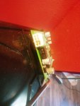
Some pics of what is melted and/or broken would be helpful. Maybe I can suggest a fix without replacing everything.
I would then try running the IpH controller and IC, with the IpH disconnected, to further eliminate the source of the problem.
You cannot run the controller and IpH alone, unfortunately, as a troubleshooting step.
Some pics of what is melted and/or broken would be helpful. Maybe I can suggest a fix without replacing everything.
- Nov 12, 2017
- 12,636
- Pool Size
- 12300
- Surface
- Plaster
- Chlorine
- Salt Water Generator
- SWG Type
- Pentair Intellichlor IC-40
The fact that there is enough current to melt the connector but not enough to pop the fuse in the IpH/IC power supply is very odd.
Those two connector parts are replaceable, if you know how to solder, and can be careful when soldering on the circuit board. The trick would be finding the parts. You're not going to get them out of Pentair. The board was put together elsewhere (probably China), so even Pentair wouldn't have access to them. You can try googling "eight conductor circuit board connector" and see what pops up. If you can find the male part, one that fits the part of the new board, you could probably strip and tin the existing wires and jam them into the connector. Each connector is slightly different how that works, but it's doable.
Frankly, before I bought a new controller, or even the replacement circuit board, I would remove the connector from the existing circuit board (unsolder it), then cut off the other connector from the wires, and solder the bare wires right to the board. You might need to solder a pin to the board, then solder the wire to the pin, using heat shrink tubing to insulate the wires from each other. You really have nothing to lose if you get it wrong.
Of course, I'm speaking as one who has that skill set and the tools to un-solder and solder on a circuit board. It's not difficult, but it's the kind of thing you have down the second time you do it.
But, of course, before you attempt any of that, you have to first find what is causing the over-current problem. Since you already replaced the controller, along with the fact that there is probably not anything on that circuit board drawing that kind of current, I'm suspecting the motor in the IpH itself. It might also be the SWG, but I'd start with the motor. Which is why I gave you the troubleshooting tip of disconnecting the motor to see if the problem goes away. If the motor is binding up somehow, or the pump components are not working smoothly, that, I think, could cause overheating in the circuit that drives the motor.
I suppose the trouble is: you don't want to connect the new board while the current problem exists, and you can't test for the problem without connecting the board. Does the old connector work well enough to get the IpH back online? If not, then I'd try soldering those wires to the old board before replacing it with the new board. Then I would run the IpH controller with the SWG plugged in, but without the IpH pump plugged in, and observe what happens. If that doesn't overheat, then plug the motor in and then monitor the heat off that black wire. If it gets too hot to touch, then it's the pump motor (or something in the pump causing the motor to work too hard).
@ogdento, any ideas?
Flying Tivo
TFP Guide
- Jan 24, 2017
- 3,100
- Pool Size
- 7500
- Surface
- Plaster
- Chlorine
- Salt Water Generator
- SWG Type
- Pentair Intellichlor IC-40
Been there,Done that and got the Hat! Eliminate the iPh control box (connect the IC60 directly) and wire the stenner directly to an available aux function.
 www.troublefreepool.com
www.troublefreepool.com
www.troublefreepool.com
www.troublefreepool.com
www.troublefreepool.com
Replacement IC-40 flow, temp sensor with aftermarket
Has anybody tried Optimum Pool Technologies for replacement sensors? They are at least half off original parts.
www.troublefreepool.com
SWG and intelliPh power bypass
When I bought all my equipment didnt know about TFP, so I bought an intelliPh to manage acid additions. After learning TFP I knew i was not going to use it too much so I only installed the Panel Box and not the pump/container itself. Well after a year of having it really dialed inn and not...
www.troublefreepool.com
IntelliPh control box down.
Control box not working, read up on @bdavis466 post about wiring through a relay. I understand the wiring, but my question is: Can i get the 26VDC from the SWG control board (this is where the PH gets its original power from)on the extra connector of my ET8 with integrated SWG transformer? Dont...
www.troublefreepool.com
Last edited:
- Nov 12, 2017
- 12,636
- Pool Size
- 12300
- Surface
- Plaster
- Chlorine
- Salt Water Generator
- SWG Type
- Pentair Intellichlor IC-40
I wouldn't say not to try that, but be aware of several things:Been there,Done that and got the Hat! Eliminate the iPh control box (connect the IC60 directly) and wire the stenner directly to an available aux function.
Replacement IC-40 flow, temp sensor with aftermarket
Has anybody tried Optimum Pool Technologies for replacement sensors? They are at least half off original parts.SWG and intelliPh power bypass
When I bought all my equipment didnt know about TFP, so I bought an intelliPh to manage acid additions. After learning TFP I knew i was not going to use it too much so I only installed the Panel Box and not the pump/container itself. Well after a year of having it really dialed inn and not...IntelliPh control box down.
Control box not working, read up on @bdavis466 post about wiring through a relay. I understand the wiring, but my question is: Can i get the 26VDC from the SWG control board (this is where the PH gets its original power from)on the extra connector of my ET8 with integrated SWG transformer? Dont...
- That doesn't solve for why the system is drawing too much current. You still have to track that down.
- You'll need a separate power supply, or figure out how to make use of the IC's transformer and otherwise step down it's voltage. If I remember right, the IpH motor uses less voltage than the IC's transformer supplies.
- The IpH injects a small amount of acid into the pool every hour. Ideally you schedule that to occur over a long period of time, all day if you can. This results is a very stable and constant pH. How well can your controller simulate that? How short a period can be scheduled? Probably not less that a minute at a time? And how many schedules are available for programming? You'll probably have to inject a day's worth of acid all at once. Which is fine, that's how most folks add acid manually, but that does cause a much larger swing of pH than adding smaller amounts 6 to 10 or more times a day,
- The IpH controller automatically halts the SWG's production of chlorine while it's injecting acid, so that the acid and chlorine don't mix together,, something that produces a very toxic gas. So you'd have to schedule the IpH to inject when the IC is off.
- The IpH controller senses flow in the 0lumbing by using the IC's flow switch, so you would lose that safety feature and you'd have to figure out how to replace that function some other way, like by installing a flow switch into the plumbing and wiring it to the IpH somehow.
- The IpH and IC are wired such that they cannot get powered up unless the pump is running, so you'd have to recreate that safety feature as well.
The IpH injecting acid into the plumbing system while the pump is off or while the SWG is on is not just bad, it's actually very hazardous.
Now, all that said, if you bypass the IpH controller, then you could use it year round. While it's connected to the IC, it stops injecting acid when the SWG stops producing chlorine due to cold water, if that happens where you live.
Last edited:
- Nov 12, 2017
- 12,636
- Pool Size
- 12300
- Surface
- Plaster
- Chlorine
- Salt Water Generator
- SWG Type
- Pentair Intellichlor IC-40
FYI: two of the three threads that Filipe posted show images of the same over-current problem, same burnt connector. Perhaps this is yet another problem well known to Pentair that they choose to ignore (like the funky SWG flow switches or the ridiculous lifespans of their 5G LED lights, to name a couple).
I'll have to go out tomorrow and see what my connector looks like...
I'll have to go out tomorrow and see what my connector looks like...
I only have an Aquarite cell, but I can't imagine the pH system would draw much current. The salt cells definitely draw a lot - so switching them on/off requires robust connectors. The connectors pentair used don't look too bad, but if any connector starts corroding it will increase in resistance and get too hot. I like Dirk's idea to modify what you've got before shelling out f$$$$ for a new iph, but I might try cleaning/sanding the toasty pins first of you can. Also, i don't know what kind of connectors those are but you start by searching amphenol (amp), molex, Phoenix etc and maybe you'll get a hit. If you're going to roll your own connectors check out 'Anderson power pole'.

- Nov 12, 2017
- 12,636
- Pool Size
- 12300
- Surface
- Plaster
- Chlorine
- Salt Water Generator
- SWG Type
- Pentair Intellichlor IC-40
After trying Tom's suggestion for cleaning the connector couplings, if that doesn't work...
In one of the pictures from Filipe's referred posts, you can see how the circuit board connector has pins that come out of the back of it and bend 90° down to penetrate the circuit board. If you get to the point where you want to try soldering the wires directly to the board: instead of unsoldering the connector from the board, just cut the pins at the back of it, leaving the pins as long as possible. Then solder the wires to the pins. Cover each with some heat-shrink tubing (which you slide onto the wire before you solder, then slide over the solder joint after it cools, then heat it to shrink it into place).
This would avoid having to unsolder the connector (which is not easy without the right tool) and also it would avoid trying to solder thick wires into the tiny holes of the circuit board. If the increased resistance from corroded connector couplings is the problem, then bypassing both the male and female connectors altogether would solve for that.
YouTube has a ton of how-tos for soldering and using heat-shrink tubing.
Last edited:
So, my update is, after a couple hours searching on the "Google" I am waiting for connector parts to arrive to replace the connector in the Ph box to circuit board. As I stated before I have a new circuit board. I am going to use dielectric grease on the contacts after replacement and see where this goes. I figure a real quick actuation of the acid pump will tell me if the pump is also a problem.
Wish me luck !!
Wish me luck !!
Flying Tivo
TFP Guide
- Jan 24, 2017
- 3,100
- Pool Size
- 7500
- Surface
- Plaster
- Chlorine
- Salt Water Generator
- SWG Type
- Pentair Intellichlor IC-40
I tried that and there are so many pins that my soldering gun stared to burn the board. Im not very knowledgeable in soldering, but if you have the skill go for it. My reasoning is that the connector is just not rated for that amount of current that goes through it. Its not that the IC is overdrawing current. Mine has been working almost 6 months without any problems.I am waiting for connector parts to arrive to replace the connector in the Ph box to circuit board.
- Nov 12, 2017
- 12,636
- Pool Size
- 12300
- Surface
- Plaster
- Chlorine
- Salt Water Generator
- SWG Type
- Pentair Intellichlor IC-40
You can definitely burn or damage a printed circuit board by applying too much heat. Not all soldering irons are created equal, though I'm not sure exactly how they are rated. Be sure to use one that is appropriate for PCBs. Apply it to the joint to be soldered as quickly as possible. Let the board cool down between solderings.
the new(er) lead free solder is a bit harder to work with than the old school leaded stuff. I put a bit flux on the joint (electronics, not plumbing flux!!) and then use a small blob of solder on the iron tip to get the joint melting quicker.
irons are rated in wattage... mine's an inexpensive 20 watt Weller with interchangeable tips... I try to use the smallest tip I can get away with, but if I'm working on a big connector or a part connected to a lot of copper I'll use a bigger tip to get more heat.
and good luck to @riverlvr!
irons are rated in wattage... mine's an inexpensive 20 watt Weller with interchangeable tips... I try to use the smallest tip I can get away with, but if I'm working on a big connector or a part connected to a lot of copper I'll use a bigger tip to get more heat.
and good luck to @riverlvr!
Flying Tivo
TFP Guide
- Jan 24, 2017
- 3,100
- Pool Size
- 7500
- Surface
- Plaster
- Chlorine
- Salt Water Generator
- SWG Type
- Pentair Intellichlor IC-40
The problem i had is that you can not heat all 8 pins at the same time to release it from the PCB. Hind sight would be to cut the connector pins and then extract each pin separately.
- Nov 12, 2017
- 12,636
- Pool Size
- 12300
- Surface
- Plaster
- Chlorine
- Salt Water Generator
- SWG Type
- Pentair Intellichlor IC-40
Watts! Duh. Thanks Tom. Yes, a lower wattage solder iron will be less grief on a delicate PCB. Here's the other "secret" to desoldering, a solder sucker:
So, my update is, after a couple hours searching on the "Google" I am waiting for connector parts to arrive to replace the connector in the Ph box to circuit board. As I stated before I have a new circuit board. I am going to use dielectric grease on the contacts after replacement and see where this goes. I figure a real quick actuation of the acid pump will tell me if the pump is also a problem.
Wish me luck !!
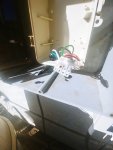
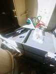
Ok, so my new plug and connector pins finally arrived. I also purchased a crimper for the connectors and clipped the plug off the power box, installed the new connectors and slipped them into the new plug housing. Installed with die-electric grease and all appears to be normal again. Systolic pump appears to run normally. Time will now tell !
- Jul 21, 2013
- 65,109
- Pool Size
- 35000
- Surface
- Plaster
- Chlorine
- Salt Water Generator
- SWG Type
- Pentair Intellichlor IC-60
Ok, so my new plug and connector pins finally arrived. I also purchased a crimper for the connectors and clipped the plug off the power box, installed the new connectors and slipped them into the new plug housing. Installed with die-electric grease and all appears to be normal again. Systolic pump appears to run normally. Time will now tell !
For others who find this thread and have the same problem can you post links to connector parts and tools you got?
- Nov 12, 2017
- 12,636
- Pool Size
- 12300
- Surface
- Plaster
- Chlorine
- Salt Water Generator
- SWG Type
- Pentair Intellichlor IC-40
For others who find this thread and have the same problem can you post links to connector parts and tools you got?
The company name is TE.com , part # for plug is 770759-1 (08P MINI UMNL PLUD HSG) , the pin socket part # is 1-794407-0 ( MINI UMNL SOK 20-16 AWG AU LF)
they also showed the connector for the circuit board, however I did not need that as I had purchased a new board.
Crimper was from Amazon (Dupont Crimping Tool Qibaok Pin Ratcheting Crimper
Hope that helps.
Thread Status
Hello , This thread has been inactive for over 60 days. New postings here are unlikely to be seen or responded to by other members. For better visibility, consider Starting A New Thread.