Pentair IC40 install with EasyTouch 8 sanity check

A,

I suspect the problem is your schedule... For the Pump/Filter relay to close, the system has to be in AUTO and the Pool or Spa mode, and the pump needs to be running (or at least supposed to be running..

My guess is you have something like this..

Pool 8 am until 11 am ..... SWCG will be on
Cleaner 11 am until 1 pm .... SWCG will be off
Pool 1 pm until 8 pm ...... SWCG will be on..

You need...

Pool 8 am until 8 pm
Cleaner 11 an until 1 pm

Thanks,

Jim R.
 
Hey Jim,
Still trying to troubleshoot the issue. Even in Auto with the pump running I wasn’t getting any LEDs to light up on the IC40. Weirdly though in the ScreenLogic app I was getting a 9900ppm salt reading for Intellichlor which was always 0 before, it’s definitely incorrect as I only added enough salt for ~3000ppm. I was getting that reading even though the IC40 showed no life.

Does the IC40 connector with the 4 pins need to line up with the power lead as I just noticed the tiny numbers 1 to 4? I didn’t check these before, but I just lined them up and the IC40 still doesn’t light up but the salt reading is back at 0ppm.

Would testing the IC40 with an ohmmeter to rule out an electrical issue make sense. Do you know which pins are live and neutral?
 
A,

I don't have a clear understanding about the 4 pin connector... :scratch:

Basically, the Filter/Pump relay closes which sends power to the SWCG Transformer.. The Transformer supplies about 24 Volts AC to the Power supply card (Surge card).. the Surge card changes the AC voltage into about 40 volts DC.. This DC voltage is what powers the Cell itself.. The Cell also gets com port data signals..

Here is a pic of my Surge card.. Yours may be different but it needs to have to same basic voltages.


The white plastic connector is the one that goes to the cell.

You can see it labeled as J7 and it has 39 VDC, Gnd, then + Data and -Data from the com port..

What you see in ScreenLogic (0 and 99999) is just bogus.. It is not valid info unless all the light on the cell are working.

Thanks,

Jim R.
 
Thanks again Jim. I did more testing last night and but couldn’t work out what was wrong. I wake up this morning and the app is reading 3650ppm salt. It appears the IC40 is only getting power when the Pool Cleaner is on. I’m guessing this is because of the way the relays are configured?

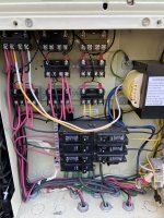
This is how it’s setup now:
BEEEF3D7-DE55-4BC2-8C8D-4A4908985D84.jpeg
 
A,

What else is connected to your Pump/Filter relay.. the relay in the upper left

I suspect that you have your Pump/Filter relay plugged into the the wrong connection on the main board.

Each relay can physically be plugged into any relay connection, but for the system to work each relay must be connected to the correct connection.

In theory the relays should be configured like this...

Upper left, is the Pump/Filter relay, then moving left to right is the Aux 1 relay, then Aux 2

The next row down is the Aux 3, then Aux 4 relay

The next row down is the Aux 5, Aux 6 and bottom right is the Aux 7..

Make sure the each relay is plugged into the correct port..

Thanks,

Jim R.
 
  • Like
Reactions: ajgraham
Just done some wire tracking which has me more confused.

Pump/filter relay is connected to J9, which has Heater (pin 1) and Cleaner (pin 2) connected.

Aux 5 relay is connected to J8, which has the main pump on pin 3.

I don’t know why it was done this way. I’m assuming from what you said Jim that normally for the pump/filter relay you’d have the filter pump on pin 1 and 3, with the IC40 on 2 and 4, and it’d would be connected to J8?

I’d then have 4 relays not hooked up to anything that I could connect the heater and pool cleaner to?
 
Ok,

It appears the guy who wired up your EasyTouch decided to not follow the normal relay location guide.. Let's see what we have..

The relay in the upper left should be the Pump/Filter relay, but is actually the Aux 1 relay.. Aux 1 is your cleaner and that is why the IC40 only come on when the cleaner is on.

Since Aux 5 is connected to J8, that makes it the Pump/Filter relay. If we have both counted the same way, we are talking about the relay in the lower left is plugged into J8.. If so, this makes the relay in the bottom left your Pump/Filter relay..

Just leave the J8 and J9 connections just as the original installer had them.. all you need to do to fix your IC40 problem is remove the yellow and white wires from the upper left relay pins 2 and 4 and move them to the lower left relay, pins 2 and 4..

The relays will work in any position, but if it is not done per the diagram on the door the next guy has no clue how it is wired.

Try that and tell me if that fixes your IC40 problem.

Thanks,

Jim R.
 
  • Like
Reactions: ajgraham
Thanks again Jim, that makes sense to me.

I was thinking along the same lines (no pun intended) about correcting it so it matches the wiring diagram. I’ll try and do this if I have time tomorrow.
 
So I rewired the IC40 to the other relay and it works as expected, just nailing down the settings so I’m not under/over chlorinating.

Huge thanks to @Jimrahbe especially, as well as the other posters who helped with advice and guidance.
 
  • Like
Reactions: Jimrahbe
Thread Status
Hello , This thread has been inactive for over 60 days. New postings here are unlikely to be seen or responded to by other members. For better visibility, consider Starting A New Thread.