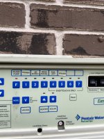
Pentair IC40 install with EasyTouch 8 sanity check

ajgraham

Bronze Supporter
Mar 14, 2021
21
Woodlands, TX
Pool Size
15000
Surface
Plaster
Chlorine
Salt Water Generator
SWG Type
Pentair Intellichlor IC-40
Hi all,
Have ordered the following kit that I hope to receive in the next couple of days:
  • Pentair IC40 520555 ($600)
  • FlowVis GPM Flow Meter Valve for 2" ($110)
  • PVC Schedule 40 2" fittings and piping
  • 8 gauge copper grounding wire
Have also got a saw, sander for chamfering pipe joins, pipe cleaner, primer and heavy duty gray cement. This is my first bit of pool DIY so I'm not experienced but have spent many hours researching planning, hydrodynamics, best practices, etc so I think I'm about as prepared as I can be without having an experienced person to consult with. That's where I'd really appreciate anyones input on any install issues you envisage a novice like myself might face particularly regarding the electronics with the EasyTouch8 control panel. I have the installation guide from the Pentair website that I'll use as reference.

I'm planning on installing it between the heater and diverter valve, removing the current check valve (no point in having 2 in that area?) and feeder and putting in a sweep elbow to improve the flow in that area. I'll make sure the spacing between the SWG and flow meter valve is sufficient based on install instructions. I'll also remove the wiring remnants of the Ozone generator which was removed by previous owner but not fully removed so I no longer have a terminal box hanging off the wall (currently behind the filter).

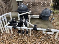
Here are images of the install area:
IMG_1668.jpgIMG_1637.jpg
 
Very nice equipment pad layout. Your ideas are good. Ensure your sweep elbow is rated for same as Sch. 40 pipe (some sweep elbows are for drainage and thus very low pressure rating). I think anything you can to do to make a more of a direct line from the heater to the diverter valve would be great as you have 3 90deg elbows there now. One best practice is to put it all together by friction fit (no primer or cement) and just ensure you got everything before you make the first cut.
Also, I assume you are putting unions on either end of the SWCG. You may want to make a dummy pipe at this time as well so if you ever had to remove the SWCG you would have that dummy pipe to place directly in that gap and maintain circulation. Then use a floater with pucks or liquid chlorine until SWCG is back operational.

Not required but some people do put in a heater bypass. Now would be a good time to do that but you will need a valve, a check valve and possibly a tee as well.

I cannot help on the electronics but good luck.
 
  • Like
Reactions: ajgraham
The SWCG you show is for the cell only (good price too). Does your EasyTouch have the SWCG power center integrated in it? Can you get the p/n off the inside door?
 
  • Like
Reactions: ajgraham
Thanks @HermanTX and @mknauss for the time and insight. It's exactly what I needed.

@HermanTX I didn't know anything about pools when we bought the house 2 years ago but I've realised since we lucked out in most regards as it looks like whoever built it knew what they were doing. Will double check all the fittings to make sure they are Schedule 40, should receive them in the next day or two.

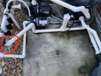
Great idea about the unions, dummy pipe and heater bypass. I'm going to do more research and work out the layout to factor those in. I did read something about heater bypasses but didn't think about doing it, but it makes sense as I'm working in that area anyway and it makes no sense to have water damaging the heater for 9 months of the year. I was wondering about how I'd go about removing the 45 deg fitting that is connected to the diverter highlighted in the picture below, I think there's only ~1 inch of pipe between the diverter and 45 deg fitting. Should I just leave it there and add another 45 deg fitting so I can straight pipe across towards the filter/heater?

IMG_1679.jpg
 
The SWCG you show is for the cell only (good price too). Does your EasyTouch have the SWCG power center integrated in it? Can you get the p/n off the inside door?
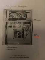
The product number is 520474 Rev. E. Weird thing is according to Pentair website this product doesn't exist having Googled it and found someone else asking Pentair about that product number. Is that because it's too old for them to know? The EasyTouch inside door did have a wiring diagram for Intellichlor installation if that helps?

I appreciate your expertise with this as I might have wrongly assumed I didn't need the external power center.
 
Last edited:
I was wondering about how I'd go about removing the 45 deg fitting that is connected to the diverter highlighted in the picture below, I think there's only ~1 inch of pipe between the diverter and 45 deg fitting. Should I just leave it there and add another 45 deg fitting so I can straight pipe across towards the filter/heater?
I agree. That was not clear in that first set of pictures. To remove that 45 deg fitting you would need to replumb everything downstream of that. You can make it work with keeping that fitting and cutting that straight somewhere past the "return" sticker on it.
Just so you are aware, the check valve that you have on line exiting the heater is there because of the inline chlorinator. It is sometimes placed directly before the chlorinator but whoever plumbed your setup elected to put it completely separate. You may be able to save that one if you desire. The only issue is that it cannot be easily disassembled to ensure it is functioning so if you got a better check valve that the top can be removed then probably best to use the new one.

The heater bypass is good if you need to drain the heater or take it out of service. As in this past Valentine Freeze, you could have put it on bypass, drained the heater and know that was good. Your plumbing will get a little more complicated with it but it looks like you have plenty of room to make it work if you add that to your project scope. Please read this to get some ideas and guidance on heater bypass.

Also, without a chlorinator, just use a floater with pucks or liquid chlorine if your SWCG is not functioning. Remember a SWCG will shut off when water temp is below 52 degs (I think it around that number) so you will have to do some "manual" addition of chlorine in the colder winter month (week?) we get in Houston at times.
 
  • Like
Reactions: ajgraham
I appreciate your expertise with this as I might have wrongly assumed I didn't need the external power center.
The ET8 Pool/Spa system without the IC system is part number 520540
The ET8 Pool/Spa system with the IC40 system is part number 520543

If there is no SWCG installed in the system at present, it is not likely that the ET8 you have has the SWCG power center in the unit. If you feel comfortable, remove the panel covering the electrical bay of the ET and post a picture of it. The SWCG power center will be obvious if there.

I believe you need the Pentair Intellichor IC40 Complete System, part number 520555-520556

You will also need a cord to connect the power unit to the ET8
 
  • Like
Reactions: ajgraham
The ET8 Pool/Spa system without the IC system is part number 520540
The ET8 Pool/Spa system with the IC40 system is part number 520543

If there is no SWCG installed in the system at present, it is not likely that the ET8 you have has the SWCG power center in the unit. If you feel comfortable, remove the panel covering the electrical bay of the ET and post a picture of it. The SWCG power center will be obvious if there.

I believe you need the Pentair Intellichor IC40 Complete System, part number 520555-520556

You will also need a cord to connect the power unit to the ET8

Had some time this evening so could make progress. You were absolutely right, it doesn't have the built-in power center. Doing more research, I bought:
  • IntelliChlor Transformer 520722
  • IntelliChlor CG Board 520723
  • SCG Resettable IOA Circuit Breaker 520714Z
  • Power Cable 520724
I got those for a little less than the cost of the external power center thanks to some internet trawling, but they'll integrate into the EasyTouch box instead of having another external unit. I used this parts PDF as reference for my older version EasyTouch. I think (and hope) that's all I'll need.

Thanks again for the help. Will update with more info and images once I've got it installed; probably next week.
 
  • Like
Reactions: mknauss
Should I just leave it there and add another 45 deg fitting so I can straight pipe across towards the filter/heater?

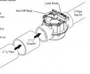
You can, but if you want to come straight off that valve port (the diverter), you most likely can do that, too. Most valve ports are designed to accept a 2" pipe on the inside, and a 2-1/2" coupler on the outside. So you could then use a reducer to get you back down to 2". You just need to make sure you have the right kind of valve to do that with before you cut the pipe. If the outside circumference of the port is 9", you're good. Like so:

jandy.pngScreen Shot 2021-03-18 at 11.56.04 PM.png

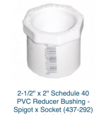
Instead of the 2-1/2" pipe shown in the bottom left, you'd glue in a 2-1/2 to 2" reducer. If you want to give it a try, either post the brand and model of the valve, or buy the parts and bring them home and measure circumferences to double check the fit before you cut the pipe. You'll cut the pipe flush with the port, and once you do there is no reusing the inside of the port (not without much trouble, that is). So know cutting until you know the coupler will fit the outside of the port. If it's a Jandy or Waterway valve, you're good to go.
 
Last edited:
With your plumbing (like most pools') flow is constant anywhere in the pipes. So you can put that FlowVis anywhere and get the same reading. Mine is just before my filter. Yours could go there, or just after the filter, or after the heater. I think you know: a Vis is a check valve, so if you need a check valve somewhere, put it there. Is a solar heater in your future? Solar goes between the filter and the heater, and would need a check between the filter and solar supply line. So that'd be a good spot for a Vis if solar is a possibility.

Screen Shot 2021-03-19 at 12.25.48 AM.png

As long as you're removing your existing tab feeder, you can safely ignore the warnings above about #4 and #5 positions. If the tab feeder is staying, your FlowVis shouldn't be near it.

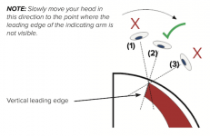
More importantly, for now, anyway, is the visibility of the scale. It's not like a pressure gauge, your eye must be just so relative to the Vis in order to get a proper reading. You view a Vis from the curved side, so keep that in mind for placement. You'll probably have to crouch a bit to line up your eye just right. It also means your eye will need to be in a different spot depending on flow rate! So you need good visual access to the entire range of that curve.

Screen Shot 2021-03-19 at 12.23.00 AM.png
 
Last edited:
  • Like
Reactions: ajgraham

Enjoying this content?

Support TFP with a donation.

Give Support
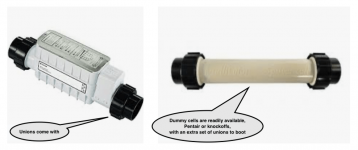
Lastly, the Pentair SWG you're installing has unions built-in. There is no need to put in two more. Pentair sells the dummy pipe of the exact dimension you'd need if you think you'd ever need to remove it. Possibly for repair? But where you live there is no real need to remove your SWG for the winter. Well, maybe this last winter! But not normally. My SWG stays put all year round.

Screen Shot 2021-03-19 at 12.40.51 AM.png

NOTE: Pentair union threads are proprietary, so you can't make your own dummy. The dummies are not as cheap as they should be, but hey, it's for a pool, so, you know, double is fair! 🤪
 
Last edited:
I used the dummy cell when I did my IC60 vertical install. It was easier to manipulate things when dry fitting and doing the final install. I did not want to damage my IC60 during construction and the dummy cell is a lot lighter than the IC60. After all the piping was installed I just swapped the IC60 for the dummy cell and everything fit perfect. The dummy cell is worth the 50 bucks or so in my opinion.

Gary
 
Last edited:
Thanks @Dirk and @gary300, I didn't think about having the dummy unit for winter but I will buy one or put in another section to swap out. Probably 2 of the last 4 winters I would have needed to switch it out so I will need one.

Regarding the electrical installation, I received the electrical parts and in the Pentair leaflet/manual that came with them it mentions an EMI filter repeatedly and even shows it in pictures:
IMG_1695.jpg

I've not been able to find out anything about that part, has it been integrated into the transformer now? Anyone know if it or another EMI filter is recommended still? Searching on the internet for more info generates nothing useful from my searching.

Saturday is D day, planning on at least doing the electronics then to make sure there's no issues and the cell lights up. Then I'll be confident on starting the plumbing the next day.
 
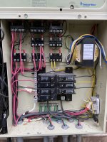
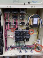
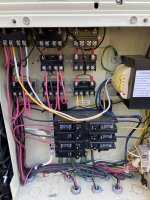
I have almost finished the electronics install, but I’ve gotten as far as my skill level can take me. I just have the 4 wires from the transformer to connect to the relay. I’m fairly sure my system is setup for 120V so was going to setup the Intellichlor transformer for 120V too. I’ve already installed the electronics in the low voltage area.

I read that I’m meant to connect the SWCG to the same relay as the main pump? If that’s relay #1 then it looks like I have 3 devices connected (main pump, heater, and I think the cleaner). Am I right in thinking relay #6 extends #1 already so I could connect the yellow+black and white+violet to #6?

Any help is much appreciated.

D848E997-4924-4A1F-94C2-153BF3F22715.jpeg43CA53A9-E362-4E57-8DC5-63F92F296CDE.jpeg
 
The main pump power is not physically run through the Pump/Filter relay. It should be direct wired from the breaker.

The heater also does not have to be run through a relay. It can be direct wired from a breaker. The Firemans Switch is then connected to the ET and thus the heater will only run when the ET closes the Firemans Switch. The Intellichlor power is run through the Pump/Filter relay so it only receives power when the pump is operating in Pool Mode.
 
  • Like
Reactions: ajgraham
Aj,

Starting with the relay in the upper left they are:

Pump/Filter relay, then Aux 1 then Aux 2
(Next row) Aux 3, Aux 4
(Next row) Aux 5, and Aux 6. Aux 7

The relay that you are calling #6 is actually the Aux 5 relay.. It is being used to turn on the spillway.. The relay itself is not being used except to connect some wires... You CAN NOT use it to run your SWCG transformer as it only energizes when someone turns on the spillway..

The SWCG transformer MUST be wired to the load side of Pump/Filter relay

I can't understand why you have your heater runs through the pump/filter relay, as it is just not needed.

My guess is that your pump/filter relay is wired for 240 volts AC.. Do you have a voltmeter???

It is IMPERITIVE that you know if the relay is wired for 120 or 240 volts AC before you connect any of the wires.

There should be a diagram on the inside of the door that shows exactly how to wire the transformer for 120 or 240 volts AC..

If you have 240 volts between pin 1 and pin 3 of the pump filter relay, then you connect the White transformer wire to pin 2 and the Yellow transformer wire to pin 4 of the Pump/Filter relay.. The Violet and Black wires get connected together with a wire nut.

If your have 120 volts between pin 1 and pin 3 of the pump filter relay, then you connect the Yellow and Black transformer wires to pin 2, and the Violet and White transformer wires to pin 4 of the pump/filter relay.

Better to make sure you are doing this correctly rather than blowing up the transformer.

Thanks,

Jim R.
 
  • Like
Reactions: ajgraham
Thanks @Jimrahbe, have just managed to do some more exploring based on your feedback.

I tested the voltage on the main relay pins 1 and 3, it's 240V. What I don't understand is that the main transformer is wired for 120V (yellow is capped). I've circled the photo below to show Black, Violet and Yellow wires from the main transformer. I thought the wiring of the main transformer dictated the voltage set? Should I just wire the SWCG transformer for 240V and be done with it?
IMG_1734.jpg
 
A,

I agree that your system transformer is wired to I20 VAC... This has no bearing on what voltage you use to power the SWCG transformer..

You can have both transformers wired for 120 VAC, or you can have both transformers wired for 240 VAC, or you can have one wired to 120 VAC and the other wired to 240 VAC.. It does not matter.

It just makes sense to me that if the Pump/Filter relay is wired to 240 VAC, that you would wire the SWCG transformer to 240 VAC.

No matter what voltage you (properly) wire to a transformer, the output voltage will be the same...

Thanks,

Jim R.
 
Thanks Jim, that’s what I wasn’t understanding. Thanks for the explanation, I will wire it for 240V and report back once I’ve finished with the install 😀
 
Did the full install today, plumbing is water tight.

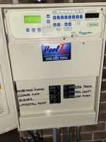
Only issue is the IC40 isn’t getting power consistently. I’ve connected the transformer to the pump relay pins 2 and 4 for 240v. Even when the pump is running the IC40 is only getting power sometimes, I confirmed this by testing the voltage on pins 2 and 4 to rule out the IC40 being faulty.

Using a Wago lever nut for black and violet wires.

Can anyone see what I’m doing wrong?
F74CA747-C5B6-4A5A-B437-EDC76D635AC8.jpeg
 

Enjoying this content?

Support TFP with a donation.

Give Support
Thread Status
Hello , This thread has been inactive for over 60 days. New postings here are unlikely to be seen or responded to by other members. For better visibility, consider Starting A New Thread.