
Jandy LRZ Ignitor too hot?
- Thread starter Martyd
- Start date
-
- Tags
- ignitor fail
You are using an out of date browser. It may not display this or other websites correctly.
You should upgrade or use an alternative browser.
You should upgrade or use an alternative browser.
- Jul 21, 2013
- 65,496
- Pool Size
- 35000
- Surface
- Plaster
- Chlorine
- Salt Water Generator
- SWG Type
- Pentair Intellichlor IC-60
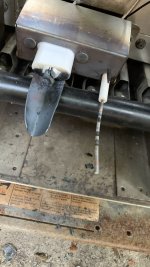
What is the voltage going to the ignitor?I have a Jandy LRZ heater. The igniter shroud keeps melting and now the igniter has melted.
There are no obstructions in the flue or exchanger and none of the fusible links are tripping.
swamprat69
Well-known member
That does not appear to be caused by the ignitor. The ignitor is not powered constantly. I would think it was caused either by overfiring (excessive heat) or or partial flame rollout (poor flame pattern).
Flame pattern seems good. Good solid blue flames. Nothing rolling out the front. How can I tell if it’s over firing? Isn’t the valve either on or off with no adjustment?That does not appear to be caused by the ignitor. The ignitor is not powered constantly. I would think it was caused either by overfiring (excessive heat) or or partial flame rollout (poor flame pattern).
Voltage at the ignitor should be between 105 and 130V. The damage looks like flame roll-out as well.220V
Did you measure this or are you making assumptions?220V
swamprat69
Well-known member
Overfiring can be caused by incorrect orifices or incorrect gas pressure to the burners from the gas valve regulator. Partial rollout ( not enough to trip the rollout switch { fusible link} ) can be caused by a partial blockage of the heat exchanger or incorrect gas/air mixture. Noticed that the flame sensor is also warped! Ignitor temp is normally ~ 2500 degrees F. NG flame temp is normally ~ 3600 degrees F. In normal operation of the heater the byproducts of combustion (heat,carbon dioxide and water vapor if combustion is complete) is supposed to move away from the burners toward the vent ( away from the burners, ignitor and flame sensor). Damage seen to the parts in the photo are an indication that something is off in one or more of these areas.
It can be either 120 or 240 according to the manual. The feed into the heater is 240 therefore I have to connect it to the 240 port on the controller, which I have.Voltage at the ignitor should be between 105 and 130V. The damage looks like flame roll-out as well.
The flame rollout sensor is functioning properly and has not tripped (melted). The sensor above the heat exchanger has not tripped either.

With the igniter energized, there will be voltage of 102-132 VAC supplied by the ignition control, test point 13 and test point 10, if the heater is connected to a 120V supply.
If the heater is connected to a 240V supply, there will be voltage of 102-132 VAC supplied by the ignition control, test point 12 and test point 10, with the igniter energized.
This voltage will be applied only during igniter heat up or trial for ignition.
Even if voltage has been confirmed at the end of the safety circuit, the “trial for ignition” sequence is imposed by the ignition control.
This sequence consists of a 15 second period of pre-purge, a 40 second period for heat-up of the igniter and a seven (7) second trial for ignition.
During this last 47 seconds there is voltage between test point 13 and test point 10, or between test point 12 and test point 10.
If satisfactory ignition is not achieved, the igniter is turned off and the system waits for a 15 second inter-purge period.
The system may go through this cycle as many as three (3) times, but thereafter it is “locked out” by the ignition control for a one hour period.
Additional attempts will be made only if the call for heat is interrupted by turning off electrical power or setting the control to “Off” and then back to "Pool" or "Spa" or after the one hour delay.
To trouble shoot the ignition control's igniter, observe that the normal ignition sequence takes place.
After the 15 second pre-purge, note the voltage between test points 13 and 10, or test points 12 and 10.
Then look for the glow of the igniter through the view port on the right side of the combustion chamber.
If the correct voltage is detected between points 13 and 10, or points 12 and 10 during the trial for ignition but the igniter does not glow, check the connections to the igniter.
Check the igniter with the ohmmeter.
Disconnect the IGN120 or IGN240 terminals from the ignition control and the connector at test point 10. Place one lead of the meter on each wire to the igniter.
The resistance should read between 40 and 75 Ohms at ambient air temperature.
If the meter reads outside of this range or shows an open or short circuit, replace the igniter.
If a short circuit is indicated, it is necessary to investigate further to find if the short is from the igniter or the flame sense circuit.
If voltage does not appear between points 13 and 10, or points 12 and 10 during the trial for ignition, there may be a bad connection, faulty transformer, or a short on the ignition control.
Check all connections, the transformer, and the ignition control for loose or corroded connections or failure and replace as necessary.
Last edited:

Turn heater OFF.
Disconnect Igniter at C & D. Turn heater ON.
Check voltage in the connector ends of C & D going to the Ignition Control (not to the Igniter).
If your meter is a true RMS meter the voltage should read 105 to 130 VAC.
If your meter is not a true RMS meter the voltage should read 64 to 130 VAC.
If the voltage is within range replace the Igniter.
If the voltage is low recheck incoming power.
If the voltage is above 130 VAC replace both the Igniter and Ignition Control.
The ignition controller modifies the input 240 volts to a 120 volts output to the ignitor.The feed into the heater is 240 therefore I have to connect it to the 240 port on the controller, which I have.
The modified voltage is not a normal sine wave and it is not read correctly by a regular averaging voltmeter.
An analog meter or a true RMS meter will read the voltage better than a regular (Non-True-RMS or averaging) digital meter.
The flame itself looks good. Nice and blue and straight. Is the bottom of the flame supposed to be above the igniter?That does not appear to be caused by the ignitor. The ignitor is not powered constantly. I would think it was caused either by overfiring (excessive heat) or or partial flame rollout (poor flame pattern).
Thread Status
Hello , This thread has been inactive for over 60 days. New postings here are unlikely to be seen or responded to by other members. For better visibility, consider Starting A New Thread.
Similar threads
- Replies
- 10
- Views
- 343
- Replies
- 3
- Views
- 176
- Replies
- 23
- Views
- 293
- Replies
- 1
- Views
- 70
- Replies
- 3
- Views
- 367