
Intex SF80110-2 Pump/Filter Timer Bypass
- Thread starter Britten
- Start date
You are using an out of date browser. It may not display this or other websites correctly.
You should upgrade or use an alternative browser.
You should upgrade or use an alternative browser.
- Status
- Not open for further replies.
Chunkybeardad
New member
My display has no life at all I want to bypass the timer all together, any suggestions?
Gunner2021
Member
I gave up on trying to repair so I bought a new motor. Works great and pool looks great! Worth the unexpected $200 price tag.
mr4hughz
New member
the white connector on the front connect to the buttons (yes?)
the black pins on the front side (attached picture = back side of the main control board .. text = dutch) look like the are directly connected to the chip .. (rx/tx ? or is this connected to something else ?

the black pins on the front side (attached picture = back side of the main control board .. text = dutch) look like the are directly connected to the chip .. (rx/tx ? or is this connected to something else ?
cspearsall
New member
Has anyone figured this out. I want to directly wire the motor to a plug and just control it with a wifi outlet. Can you bypass the entire control board and just use a plug connected to the motor?
RoughDraft40
Member
Yes you can bypass the controller/circuit board. The unit uses an induction motor with a start capacitor (quite common). I'm not an electrician; however, being a bit of a tinkerer/researcher I was able to familiarize myself with the basics. All that being said, I don't take any responsibility for anyone else attempting this and this is for education purposes only. There may be alternative ways of wiring, but this is how I have my unit wired.Has anyone figured this out. I want to directly wire the motor to a plug and just control it with a wifi outlet. Can you bypass the entire control board and just use a plug connected to the motor?
Attachments
giovanni.castello
New member
I have SF70220-2 and I managed to bypass pressing on/off button to start pump by following procedure:
* disconnect power cord
* press and hold on/off button
* connect power supply cord to mains power (pump beeps)
* disconnect power supply cord
* connect power supply cord - this time (and all next) pump will start without need to press on/off button
For deactivation of autostart behaviour repeat above procedure again.
Not sure what model I have but I'm going to try this when I get home. I'd love to have 3 hrs in the morning and 3 in the evening, without having to modify the pump itself. If this works then a simple timer rated for a 1/2 HP pump will give me flexibility like this.I have SF70220-2 and I managed to bypass pressing on/off button to start pump by following procedure:
* disconnect power cord
* press and hold on/off button
* connect power supply cord to mains power (pump beeps)
* disconnect power supply cord
* connect power supply cord - this time (and all next) pump will start without need to press on/off button
For deactivation of autostart behaviour repeat above procedure again.
This does not work for my pump. Also I’m reminded that shutting off the power trips the GFCI on the plug, preventing a timer outlet from working even if the pump would auto-start
mirko
Gold Supporter
- May 19, 2020
- 29
- Pool Size
- 6000
- Surface
- Vinyl
- Chlorine
- Salt Water Generator
- SWG Type
- CircuPool Universal40
I tried this with an SF60110-2 and it did not work. It was not clear when the power (on/off) button should be released after pressing and holding it in the second step. I tried releasing the power button at different times, but still was unable to have the pump automatically start when the power turned on to the pump.I have SF70220-2 and I managed to bypass pressing on/off button to start pump by following procedure:
* disconnect power cord
* press and hold on/off button
* connect power supply cord to mains power (pump beeps)
* disconnect power supply cord
* connect power supply cord - this time (and all next) pump will start without need to press on/off button
For deactivation of autostart behaviour repeat above procedure again.
Hi All!
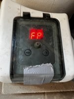
I recently bought an Intex pump SF60110-2 and it failed after only 2 days, it just beeps and shows a period on the display screen. Found this thread while searching for fixes. Intex is sending out a new pump, but I also wanted to get this one working.
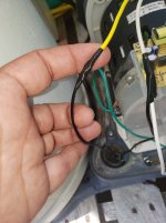
I was able to get it running by bypassing the control circuit board and display board. This is what it looked like before I removed all the wires. I wasn’t sure if the capacitor is polarized so I put blue tape on one lead so I knew which one was connected to the corner of the circuit board. You can see the display board is hanging down as well after being removed from the housing cover.

After disconnecting the wires and removing the control board this is what you are left with, 3 wires to from the motor, 2 wires from the start capacitor, and 3 wires from the power cord, not shown.

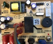
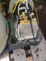
Here is a close up of the control board with labels of what was connected. Sorry for my terrible handwriting.

Close up of the rear of the control board. Its just flipped up, the bottom right corner in the top pic is now the top right corner.

Shot of the start capacitor, at least I assume it’s a start capacitor. In case the photo links get removed or archived the specs for the capacitor are:
CBB60
40 uF +/-5% SH
250 VAC DB C
50/60 Hz So
40/70/21

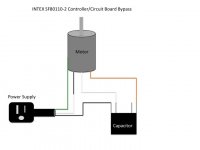
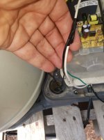
This is what I came up with for wiring to bypass the control board. I’m not sure its correct but it turns on when I apply power. I think the control board controls the on/off of the start capacitor and this wiring has it on all the time. If anyone has other ideas please share.

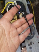
Using some 14 awg stranded wire I had with some ¼” male quick connects I made 3 connectors to connect the motor, capacitor, and power cord together.

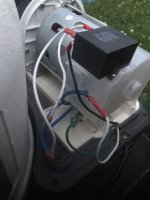
All wired up. Again, I’m not sure if this is correct but the pump does turn on and wired like this the GFCI plug doesn’t rest every time you turn power off/on.

I recently bought an Intex pump SF60110-2 and it failed after only 2 days, it just beeps and shows a period on the display screen. Found this thread while searching for fixes. Intex is sending out a new pump, but I also wanted to get this one working.
I was able to get it running by bypassing the control circuit board and display board. This is what it looked like before I removed all the wires. I wasn’t sure if the capacitor is polarized so I put blue tape on one lead so I knew which one was connected to the corner of the circuit board. You can see the display board is hanging down as well after being removed from the housing cover.
After disconnecting the wires and removing the control board this is what you are left with, 3 wires to from the motor, 2 wires from the start capacitor, and 3 wires from the power cord, not shown.
Here is a close up of the control board with labels of what was connected. Sorry for my terrible handwriting.
Close up of the rear of the control board. Its just flipped up, the bottom right corner in the top pic is now the top right corner.
Shot of the start capacitor, at least I assume it’s a start capacitor. In case the photo links get removed or archived the specs for the capacitor are:
CBB60
40 uF +/-5% SH
250 VAC DB C
50/60 Hz So
40/70/21
This is what I came up with for wiring to bypass the control board. I’m not sure its correct but it turns on when I apply power. I think the control board controls the on/off of the start capacitor and this wiring has it on all the time. If anyone has other ideas please share.
Using some 14 awg stranded wire I had with some ¼” male quick connects I made 3 connectors to connect the motor, capacitor, and power cord together.
All wired up. Again, I’m not sure if this is correct but the pump does turn on and wired like this the GFCI plug doesn’t rest every time you turn power off/on.
dvsjay
New member
you saved my life, my power button broke and with this fix was able to bypass it and run everything from a smart GFI outlet thank you thank you thank youYes you can bypass the controller/circuit board. The unit uses an induction motor with a start capacitor (quite common). I'm not an electrician; however, being a bit of a tinkerer/researcher I was able to familiarize myself with the basics. All that being said, I don't take any responsibility for anyone else attempting this and this is for education purposes only. There may be alternative ways of wiring, but this is how I have my unit wired.
bigjdaddy1
New member
Yes here is how I bypassed the entire circuit board and everything. Hope this helps people. Pay attention to the start capacitor wiring the wrong way can be bad. Do put cover back on it is needed to circulate the air on the motor correctly.My display has no life at all I want to bypass the timer all together, any suggestions
Attachments
AmazingHi All!
I recently bought an Intex pump SF60110-2 and it failed after only 2 days, it just beeps and shows a period on the display screen. Found this thread while searching for fixes. Intex is sending out a new pump, but I also wanted to get this one working.
I was able to get it running by bypassing the control circuit board and display board. This is what it looked like before I removed all the wires. I wasn’t sure if the capacitor is polarized so I put blue tape on one lead so I knew which one was connected to the corner of the circuit board. You can see the display board is hanging down as well after being removed from the housing cover.
View attachment 359034
After disconnecting the wires and removing the control board this is what you are left with, 3 wires to from the motor, 2 wires from the start capacitor, and 3 wires from the power cord, not shown.
View attachment 359035
Here is a close up of the control board with labels of what was connected. Sorry for my terrible handwriting.
View attachment 359037
Close up of the rear of the control board. Its just flipped up, the bottom right corner in the top pic is now the top right corner.
View attachment 359038
Shot of the start capacitor, at least I assume it’s a start capacitor. In case the photo links get removed or archived the specs for the capacitor are:
CBB60
40 uF +/-5% SH
250 VAC DB C
50/60 Hz So
40/70/21
View attachment 359039
This is what I came up with for wiring to bypass the control board. I’m not sure its correct but it turns on when I apply power. I think the control board controls the on/off of the start capacitor and this wiring has it on all the time. If anyone has other ideas please share.
View attachment 359040
Using some 14 awg stranded wire I had with some ¼” male quick connects I made 3 connectors to connect the motor, capacitor, and power cord together.
View attachment 359041
All wired up. Again, I’m not sure if this is correct but the pump does turn on and wired like this the GFCI plug doesn’t rest every time you turn power off/on.
View attachment 359042
This has solved a similar issue I had whereby the circuit board failed (looked like a popped cap) and I was unable to find a replacement.
In the UK / Europe the wiring colours are slightly different - brown is live (white in this diagram) and blue is neutral (black in this diagram). Interestingly (and I have no idea why) the motor wiring colours are reversed as they are in this diagram, e.g. the blue motor wire connects to the live and the brown motor wire connects the to the neutral. The starting cap also connects to the neutral.
Thanks again for documenting this - I'm going to automate into home controls as others have done.
In the US black is hot (live) and white is neutral.In the UK / Europe the wiring colours are slightly different - brown is live (white in this diagram) and blue is neutral (black in this diagram). Interestingly (and I have no idea why) the motor wiring colours are reversed as they are in this diagram, e.g. the blue motor wire connects to the live and the brown motor wire connects the to the neutral. The starting cap also connects to the neutral.
woutervandaele
New member
When bypassing the control circuit this way, should it be possible to use a variable speed controller?
Eddyloner
New member
Check this video.Mine is stuck in Power Saving Mode. Only shows a "period" on the display. Power button doesn't do anything, and if I press the lock or timer button I hear three beeps then nothing happens.
Eddyloner
New member
- Status
- Not open for further replies.
Thread Status
Hello , This thread has been inactive for over 60 days. New postings here are unlikely to be seen or responded to by other members. For better visibility, consider Starting A New Thread.