Yes you can bypass the controller/circuit board. The unit uses an induction motor with a start capacitor (quite common). I'm not an electrician; however, being a bit of a tinkerer/researcher I was able to familiarize myself with the basics. All that being said, I don't take any responsibility for anyone else attempting this and this is for education purposes only. There may be alternative ways of wiring, but this is how I have my unit wired.
Thank you for this and the pictures. It worked. I'm not an electrician either but am not afraid to tinker.
 
? Sand filter beeps 3 times won’t start. And shows a red light. Any ideas what’s wrong and how I can get it to work. Thanks in advance.
 

Attachments

  • image.jpg
    image.jpg
    348.1 KB · Views: 4
Check this video.
Hi all,

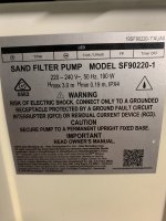
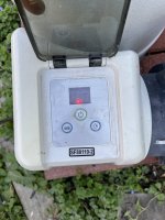
Over the past 2-3 weeks, been having trouble with the electronics in the SF70220-2 (EU/Netherlands). I encountered the dread 'Intex pumpt stuck in standby' with only the dot showing in the display and the buttons not doing anything any longer.
Whatever I tried, operation would not come back.

What I did is the following:

STEP 1:

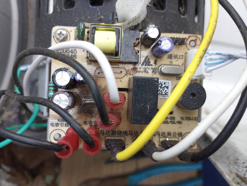
Followed the instructions in the YouTube video (thanks for sharing, moving the connector successfully bypassed the timer and brought back operation of the pump !)


STEP 2:

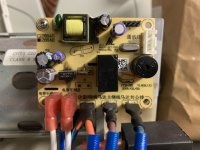
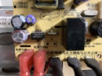
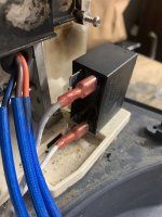
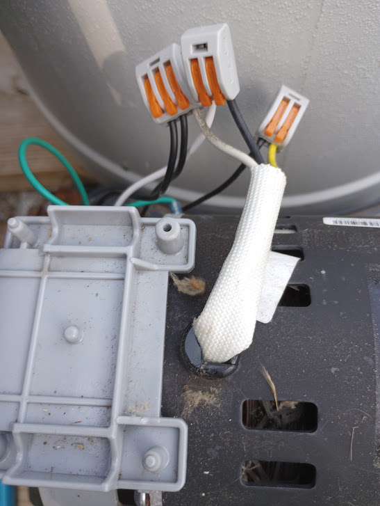
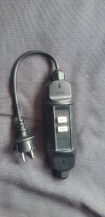
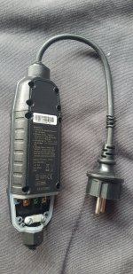
2.1 Opened the AC-mains TEST/RESUME device (integrated into the AC-cable between AC-Mains and Intex pump), removed the 3 leads on the 'Load' side.
2.2 Connected the 3 leads to a European AC-plug.
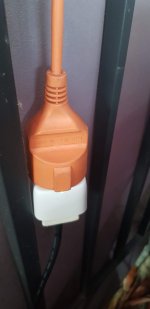
2.3 Stuck an INNR Smart Plug into the AC-mains
2.4 Stuck the AC-plug from step 2.2 into the Smart Plug from step 2.3
2.5 Integrated the Smart Plug into our Zigbee smart-home mesh network.

END RESULT:
All is working again aaannnnd the system has even been improved massivly since it is now part of our Hue/Zigbee enabled smart-home and can be controlled through the Signify Hue app !
Actions can be set in the app as well in order to program the Intex pump to run only for a couple of hours a day as intended.

Needless to say, ensure to keep AC-power and it's leads far away from water to avoid short circuits or other dangerous situations !

If I can help out anyone with more details, feel free to drop me a line.
Some photos have been added to this message as well explaining what I did.

BR Maarten
 

Attachments

  • 20220702_125411.jpg
    20220702_125411.jpg
    693.7 KB · Views: 9
  • 20220702_125423.jpg
    20220702_125423.jpg
    671.3 KB · Views: 9
  • 20220702_125452.jpg
    20220702_125452.jpg
    167.9 KB · Views: 9
Yes you can bypass the controller/circuit board. The unit uses an induction motor with a start capacitor (quite common). I'm not an electrician; however, being a bit of a tinkerer/researcher I was able to familiarize myself with the basics. All that being said, I don't take any responsibility for anyone else attempting this and this is for education purposes only. There may be alternative ways of wiring, but this is how I have my unit wired.
Thanks for the information and schematic. I purchased a new SF-80110-2 pump from Intex which arrived with a completely non-functional power/timer interface. DOA. They replaced it, however I was able to get the "old" pump working with your schematic. I use automation anyway...so no need for the onboard timer or power interface. My pump had the square cap mounted up top like yours..so your images and wiring matched up exactly. Thanks :)

intex-sf80110-2-circuit-board-bypass-real-jpg.348096


slide1-jpg.348095
 
Hey there I have a pool pump SF 90220-1

And the neutral tab blew off and I can’t find a circuit board to replace , could some one assist me in New Zealand on how to bypass the controller so I can add a Wi-Fi power point ? Many thanks Adam
 

Attachments

  • 187691A0-1128-40A4-BE4C-6CBA8AEF0C92.jpeg
    187691A0-1128-40A4-BE4C-6CBA8AEF0C92.jpeg
    374.5 KB · Views: 17
  • 78497AF3-F091-48F4-A433-DC43DE11F321.jpeg
    78497AF3-F091-48F4-A433-DC43DE11F321.jpeg
    322.4 KB · Views: 17
  • 1F74F0A7-2D1E-406A-B6E4-769B1C77DF72.jpeg
    1F74F0A7-2D1E-406A-B6E4-769B1C77DF72.jpeg
    292.5 KB · Views: 17
  • 85EB3BA2-3F06-426E-AAA1-556BF361367C.jpeg
    85EB3BA2-3F06-426E-AAA1-556BF361367C.jpeg
    298.4 KB · Views: 17
the white connector on the front connect to the buttons (yes?)
the black pins on the front side (attached picture = back side of the main control board .. text = dutch) look like the are directly connected to the chip .. (rx/tx ? or is this connected to something else ?


View attachment 327642
This photo was a life saver. I had my control board completely fried from 2 small snails that managed to get inside. Just connected up all the wires as they connect on the pcb and voila…. IT WORKS! Huge thanks!