Intermatic timer replacement and wiring fix

bob22

Well-known member
Sep 1, 2008
89
Philadelphia
Filter pump timer motor (wg1573-5) failed (no longer keeps time; clock face not turning).
Enclosure is an Intermatic T21004R. Pump is on a 15 amp, 2-pole circuit breaker.

When I removed the clock portion from the enclosure to get timer motor number, a red wire came loose (naturally, didn't spot where it was beforehand). Many of the wires were fairly loose I found out.

This is the box with the red wire that had come loose (marked S1) attached to where I think it belongs. That is terminal 1 as marked on the terminal strip. S1, S2 (black), and the white neutral (far left terminal) all originate from conduit S (goes to panel supply). M1 (red) and M2 (blk) go to motor.
IMG_1837.jpeg
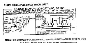
Here is diagram from door:
IMG_1830.jpeg
And diagram:
IMG_1839.jpeg
Do you agree S1 belongs where I put it on terminal 1?

Thanks!
 
Follow-up.
New motor did not allow clock to move (original problem).

I ordered a T104M mechanism from Intermatic and wired it according to the enclosed instructions.
20220725timer.jpg
Again, clock does not advance/move. What to do now?

Filter pump will turn on if I use the manual switch.

I have the electrical supply (neutral and two hots) on A (neutral) and Supply 1 on Terminal 1 and S2 on T3.
Motor leads are on T2 and T4.

There is no wire on the GR (ground) screw on the clock panel connecting to the ground on the enclosure (wasn't one on original wiring). Should there be?
 

Attachments

  • 20220725timer.jpg
    20220725timer.jpg
    79.1 KB · Views: 2
A T104M has no wiring on terminal A, not sure why your original did. From the double-pole breaker one lead goes to 1, the other to 3. You can hook a green (ground) to the screw on the panel if called for. All it takes is for one or both of the "S" wires to be on 2 and/or 4 and one or both "M" wires to be on 1 and or 3 for what you are experiencing to happen.
 
Are the two wires on terminals one and three still connected? The ones that go to the clock? Maybe add a picture of your install - like in your first post. Do you have a volt meter?
 
1poolman1, where are you saying that the neutral from the 220v panel source cable should go once it enters this enclosure?

ccbill,
Here is present configuration (added ground wire to timer board).
The clock motor wires are still connected to T1 and T3 as indicated in the diagram Intermatic provided:
20220725timer.jpg
FYI: switch controls pool light, and that circuit is fed from GFCI convenience outlet below it. These two are fed from a 120 circuit not the 220 filter motor circuit.:
IMG_1884 (1).jpeg
 
I think that the A terminal essentially connects to the plate the motor is connected to so in effect provides a path for the neutral. Otherwise, the motor would not work as all electric loads need a supply of voltage and a return. Correct?
 
I think that the A terminal essentially connects to the plate the motor is connected to so in effect provides a path for the neutral. Otherwise, the motor would not work as all electric loads need a supply of voltage and a return. Correct?
240 volt devices do not require a neutral. They use two hot legs.

120 volt devices use one hot leg and a neutral.

Your timer is a 240 volt device.

Note the wiring diagram shows nothing connected to the A screw.

20220725timer-jpg.440309
 

Enjoying this content?

Support TFP with a donation.

Give Support
I think that the A terminal essentially connects to the plate the motor is connected to so in effect provides a path for the neutral. Otherwise, the motor would not work as all electric loads need a supply of voltage and a return. Correct?
A 220/240 volt system doesn't use the neutral. Its fine if attached to A, but does nothing. If you look on the back of the timer you'll see it is empty at that terminal.
 
Ignore the first screw on the far left of your timer mechanism (don't know what that wire is doing connected to it). The remaining screws numbered 1,2,3,4 from left to right are: Line 1 (screw 1), Load 1/Pump 1 (screw 2), Line 2 (screw 3), Load 2/Pump 2 (screw 4). The two thinner white wires on screws 1 and 3 are the unswitched power feed to the 240v timer motor. Everything looks correct. The motor should be running regardless of the load switch positions. Can you hear the motor running? Are the gears to the timer dial stripped? Have you checked the voltage going into the timer screws 1 and 3?
 
That sounds a little strange - the only thing that turns any gears is the motor so if the gear is turning I would think the motor is good but maybe the gears are stripped(?)
Tiny little plastic gears do wear out on a very rare occasion. Most Intermatic timers are virtually "bullet proof" as the expression goes. Mostly happens when the trippers are too close together and the dial gets stuck.
 
I think that the A terminal essentially connects to the plate the motor is connected to so in effect provides a path for the neutral. Otherwise, the motor would not work as all electric loads need a supply of voltage and a return. Correct?
That would be incredibly dangerous. You could not touch the switch arm without danger of electrocution. "A" terminal is the neutral connection for a 120v timer motor (T101, T103) and a 120v load (light, pump). It does nothing on a T104.
 
Thread Status
Hello , This thread has been inactive for over 60 days. New postings here are unlikely to be seen or responded to by other members. For better visibility, consider Starting A New Thread.