Filter pump timer motor (wg1573-5) failed (no longer keeps time; clock face not turning).
Enclosure is an Intermatic T21004R. Pump is on a 15 amp, 2-pole circuit breaker.
When I removed the clock portion from the enclosure to get timer motor number, a red wire came loose (naturally, didn't spot where it was beforehand). Many of the wires were fairly loose I found out.
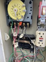
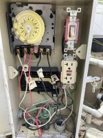
This is the box with the red wire that had come loose (marked S1) attached to where I think it belongs. That is terminal 1 as marked on the terminal strip. S1, S2 (black), and the white neutral (far left terminal) all originate from conduit S (goes to panel supply). M1 (red) and M2 (blk) go to motor.
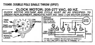
Here is diagram from door:
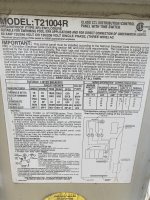
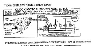
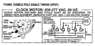
And diagram:
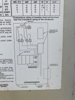
Do you agree S1 belongs where I put it on terminal 1?
Thanks!
Enclosure is an Intermatic T21004R. Pump is on a 15 amp, 2-pole circuit breaker.
When I removed the clock portion from the enclosure to get timer motor number, a red wire came loose (naturally, didn't spot where it was beforehand). Many of the wires were fairly loose I found out.
This is the box with the red wire that had come loose (marked S1) attached to where I think it belongs. That is terminal 1 as marked on the terminal strip. S1, S2 (black), and the white neutral (far left terminal) all originate from conduit S (goes to panel supply). M1 (red) and M2 (blk) go to motor.

Here is diagram from door:

And diagram:

Do you agree S1 belongs where I put it on terminal 1?
Thanks!


