Intelliflo VSF pump won't run when connected to automation via iAqualink

CMarsh

0
Bronze Supporter
Jul 14, 2018
8
Highland VIllage, TX
Installed Jandy iAqualink 3.0 (IQ30-RS) with new complete bezel & PCB Rev. Y. All the communication aspects work fine. Set up the pump in iAqualink as Pentair VS pump. Default pump speeds are set. While in auto mode, selecting on the app to start the filter pump initiates all the usual actions via valve actuators, and I hear the relay click like it always has, the pump display shows "display inactive" like normal when wired with the automation cable. The little indicator light next to the start/stop button on the pump keypad even illuminates. However, the pump does not prime nor run. Also getting the same results in service mode. All the actuators, etc. do their normal routine, but the pump does not prime/run.

I have confirmed via powering down, disconnecting the automation cable, and then powering up again that the pump runs just fine in manual or scheduled mode via the pump control pad itself (isolated from Jandy controls).

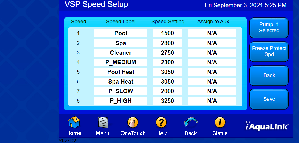
The pump address is confirmed as pump 1 on the pump display and in iAqualink.

Also confirmed the pump firmware is an earlier version (2.XX) than the problematic version I saw mentioned in another thread on TFP.

The pump control is wired correctly (green to 3, yellow to 2). No other wires are connected to that particular Jandy 4-pin connector. The other 4-pin connector has the iAqualink and the SWG wires connected to it.

Everything operates seemingly as it should save the pump itself via Auto or Service modes.

Any ideas? Thanks in advance.
 
Last edited:
C,

I know squat about your automation, but for this pump to run on a Pentair automation system the following things have to happen.

The system must be in Auto and not in the Service mode
The pump type must be correct. VS..
There must be a Circuit on.. Usually the Pool Circuit, but it can be any circuit.
The circuit that is on, must have a speed assigned. Like.. Pool = 1500 RPM
The pump's display must say "Display not Active"

Not sure how this correlates to your automation system, but maybe it will give you an idea.

The only thing that you did not mention was setting up your speeds.

Thanks,

Jim R.
 
Welcome to TFP.

Show us your VSP Speed Setup page…

Jandy_Aqualink_VSP_Speed_Setup.png
 
When you were exchanging the PCB did you connect the wires from the relays to the correct AUX sockets - starting with the filter pump?
The RS485 wire seems to be working in that you were able to set up the pump but if the Filter Pump relay is connected to the wrong AUX socket then it does not know what to do.
 
I recall a similar thread some time back. The OP finally figured out that his Jandy automation would not work with the pump in "flow control" mode. He did something with pump configuration to have automation control speed (which was all the earlier Pentair pumps allowed), and then it worked fine. The conclusion was that Fluidra's pump integration was lagging Pentair pump updates. My old brain probably has the details wrong, but I'm having trouble finding the thread.

edit
Okay. Google search provides... I think this is it. Already an old article, so seems not likely to be the problem.
 
Last edited:

Enjoying this content?

Support TFP with a donation.

Give Support
I recall a similar thread some time back. The OP finally figured out that his Jandy automation would not work with the pump in "flow control" mode. He did something with pump configuration to have automation control speed (which was all the earlier Pentair pumps allowed), and then it worked fine. The conclusion was that Fluidra's pump integration was lagging Pentair pump updates. My old brain probably has the details wrong, but I'm having trouble finding the thread.

edit
Okay. Google search provides... I think this is it. Already an old article, so seems not likely to be the problem.
Thank you. I read this, and did confirm that the pump is set to speed (not flow) via the pump control pad. Also, the version of iAqualink I'm seeing did not show options for VF or VS when setting up the pump. Rather just the Intelliflo VS as an option to select, which I did.
 
  • Like
Reactions: generessler
Thank you. I read this, and did confirm that the pump is set to speed (not flow) via the pump control pad. Also, the version of iAqualink I'm seeing did not show options for VF or VS when setting up the pump. Rather just the Intelliflo VS as an option to select, which I did.

Aqualink has only supported VS mode with Intelliflo pumps.


From Jandy Aqualink RS - Further Reading

While the Aqualink RS can control an Intelliflo VS pump it cannot control the VF functions of a VSF pump.

At one time Jandy's F/W was made to talk with the IntelliFlo VS. Then Pentair developed a new pump that was both a VS and VF pump, the VSF. Jandy's F/W has never been updated to drive the VF portion of the VSF pump.

Speculation is several years ago the Big Three (Hayward, Jandy and Pentair) decided to share their RS-485 code, so that they could control each others equipment. Not sure why that did not continue, but as time went on, the firmware running all these systems has changed, but the Big Three no longer keep this interchangeabilty in mind when they update their firmware.

This is the main reason that we always recommend the same brand for products that need to "talk" to each other. It just makes things easier for installation and warranty issue.
 
When you were exchanging the PCB did you connect the wires from the relays to the correct AUX sockets - starting with the filter pump?
The RS485 wire seems to be working in that you were able to set up the pump but if the Filter Pump relay is connected to the wrong AUX socket then it does not know what to do.
Hi. I labeled the aux socket pins as I removed them and reset them in the new PCB. I just went out and followed the wires to visually confirm that the pump is indeed in the first slot, with the cleaner in the adjacent spot. I confirmed that all the Aux equipment is in the right location, as they all respond to being turned on by the iAqualink automation. Everything except of course the pump itself turning on. Again, the panel and relay are doing all the things you'd expect when I turn the filter pump "on" via the app (same result from panel in service mode).
 
  • Like
Reactions: HermanTX
Show a picture of the Filter Pump relay and its wiring for the pump.
Photos attached of power center and relay 1 (filter pump).

An explanation here may be warranted, as the electrician who installed this in 2018 put in a GFCI (photo 1 lower left) that effectively serves as a breaker for the Jandy control and AquaRite SWG elements. Additionally he wired in a switch for pump power (photo 2 lower right), allowing independent control of power to the pump (separate from the GFCI and Jandy control circuit). This way I can run the pump even with the control system down, or power down the pump without cutting power to the control system. This is not a factor in the issue at hand, but I felt like I should explain what you're seeing since it is likely not a typical electrical power setup. That's why you see the wires going out & back at the bottom right of the power center box.
 

Attachments

  • IMG_2378.jpg
    IMG_2378.jpg
    299.1 KB · Views: 26
  • IMG_2379.jpg
    IMG_2379.jpg
    491.4 KB · Views: 7
  • IMG_2377.jpg
    IMG_2377.jpg
    509.2 KB · Views: 8
  • IMG_2376.jpg
    IMG_2376.jpg
    621.7 KB · Views: 9
  • Like
Reactions: HermanTX
I will note they it is poor technique to put more than two wires under one screw.

For more than two wires you should connect all the wires together with a pigtail and connect the pigtail to the screw.
 
Very strange, I don’t see anything wrong with the way you described your setup and connections.

A couple other things to look at, you may want to disable the pump lock out function just in case the pump is stopped because the system thinks it is changing some mode or valves. I really don’t see how this could happen, but it won’t hurt to disable the pump lockout in system setup menus.

IMG_0325.png

And then try turning the filter pump function on and then click the status button on the main web interface page. Does the system think the pump is on and running (whether it is running or not).

IMG_0326.png


And lastly try swapping the green and yellow wires around, green to pin 2 and yellow to pin 3. I know this would be backwards from the way it should be, but it’s not working when hooked up correctly (this would be really strange as it’s seeing something on the help screen.)

But at this point it can’t hurt to try and swap the pin2 and pin 3 wires around, you can’t damage anything by doing this, if reversed the data will just be garbled.
 
I will note they it is poor technique to put more than two wires under one screw.

For more than two wires you should connect all the wires together with a pigtail and connect the pigtail to the screw.
Fwiw, the AquaLink manual does at least imply 2 per screw is okay: "Never put more than two (2) wires into each of the pins of the red, 4-pin terminal bar (use a Jandy multiplex board)." (Then they ask $125 or so for the multiplex board, which is just 4 connectors wired in parallel.)
 
Fwiw, the AquaLink manual does at least imply 2 per screw is okay: "Never put more than two (2) wires into each of the pins of the red, 4-pin terminal bar (use a Jandy multiplex board)." (Then they ask $125 or so for the multiplex board, which is just 4 connectors wired in parallel.)
I was referring to high voltage wiring like here where it looks like three wires are under each LINE screw. This is more hazardous then low voltage wiring.

img_2378-jpg.582028
 
  • Like
Reactions: generessler
I was referring to high voltage wiring like here where it looks like three wires are under each LINE screw. This is more hazardous then low voltage wiring.
Ah. Sorry. Yes. Right on. Our panel also had multiple wires per screw like this when we moved in. About a year after, one of those connections arced and destroyed the relay.
 

Enjoying this content?

Support TFP with a donation.

Give Support