Intellicenter control of Intellivalves - frustrating

Feb 2, 2017
21
Lake Forest, CA
I am a bit confused on initial setup of my i8ps intellicenter and intellivalves for the following configuration:

Elevated spa spilling into pool
Single VSF pump and filter used for both pool and spa
Shared Equipment configuration - per the manual (but not mentioned anywhere in configuring that I can find)
Intake and return intellivalves with each one plumbed to pool or spa
We always have the spa spilling into pool in pool mode - intake valve set to pool and return valve set to spa
In spa mode the intake valve is set to spa and the return valve is set to spa
The valves are connected to intake and return valves connections on the intellicenter

Currently it was configured by the pool guy as two bodies labeled pool and spa
He has Valve A to pool (but nothing is connected to Valve A on the circuit board)
He has Valve B to spa (but nothing is connected to Valve B on the circuit board)
The intake and returns valve settings are greyed out set to pool/spa in the configuration

In pool mode, no valves move.
In spa mode, both valves move to the opposite.

I understand how to change the Home location of the valves. The home position of both valves is in the pool position.

I want both the intake and return valves to return to the pool location when the system is off. When turned on in the pool mode, I want the intake valve to remain at the pool location and the return valve to switch to spa location. When turned on in spa mode, I want the intake and return valves to switch to the spa locations.

The pool guy doesn't seem to understand this system, and I find the manuals a bit, well, underwhelming in terms of explaining the interfunctionality of these bits.

Can you please help me?

Thanks,
Mike
 
I want both the intake and return valves to return to the pool location when the system is off.

When the filter/pump is turned off the valves will stay in their last position.

You need to select POOL mode before turning off the system.

When turned on in the pool mode, I want the intake valve to remain at the pool location and the return valve to switch to spa location.

That is called SPILLOVER mode.

When turned on in spa mode, I want the intake and return valves to switch to the spa locations.

That is SPA mode.

You have three modes that control the suction(intake) and return valves. They are plugged into the INTAKE and RETURN sockets on the board.

  1. POOL mode - water comes from the pool intake/skimmers and out the pool returns.
  2. SPA mode - water comes from the spa suction and out the spa returns/jets
  3. SPILLOVER mode - water comes from the pool intakes/skimmers and out the spa returns/jets
 
With IntelliCenter the system should return to the pool mode with the intake and return valves in their un-diverted position if the spa circuit is not on. This means that this will be the state if neither the pool or spa are on.

First double check that the correct valve is connected to the valve connectors for the intake and return. If they are not you will be all confused by the setup. This means that the intake valve should be in the intake and the return should be in the return. Valves A and B will not matter if nothing is connected to them.

In the configuration you cannot reassign the intake and return valve. By installing the i8PS daughter card the system is automatically switched into shared body mode and the control of intake and return are hard-coded. So when neither body is turned on both valves should be in the non-diverted or pool position. There should be no flow into the spa when in this mode. However, it is possible that the PB installed a makeup line that always flows into the spa. You will need another actuator if this is the case.

Next select the spa body to turn it on. Both valves should rotate to their diverted position and the flow into the pool should stop. This is regardless of the existence of a spillway makeup line. Finally, create a feature in your IntelliCenter configuration. Name it spillway and select the function type to be spillway. You can select spillway or generic as options. After doing that return to pool mode and turn on the spillway feature. The result should be that the return valve will cycle to the diverted position and the intake will remain in the non-diverted position.

Now if you have a spillway makeup line you can add another actuator to it and put it in Valve B. Then assign the valve to the Spillway feature you created. The result is that when the spillway feature is on it should rotate the diversion so that it allows flow through the makeup line. It should not flow through the makeup line if the Spillway feature is off.
 
I want the intake valve to remain at the pool location and the return valve to switch to spa location
Mike,

That is not how the system is designed and does not make a lot of sense. If you suck water from the pool and return it all to the spa, you will have no water coming out of your pool returns. Most pool/spa have a little water that gets diverted to the spa to cause an overflow into the pool, but they don't have all the return water going to the spa.

Spa's overflow by one of three methods. Most pools/spas have what is called a make-up valve that is plumbed so that some water can be diverted to the spa in the pool mode. Some lazy pool builders just offset the Return valve so that it never closes off the spa. The third method is to set up the Spillway Function in the automation system. The spillway function is not something that you would want to run all the time.

Show us several pics of your equipment pad and we can see which option makes the most sense for you.

Thanks,

Jim R.
 
Thank you all for responding. I regret that I did not check the site from my original post until now. I did reach out to Pentair and got a similar reply regarding making a Spillway feature.

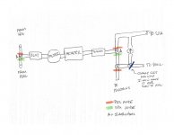
There is a crossover (make-up) line with a valve on the oulet to the pool side with a check valve to the spa side.

The issue that got me into this line of questioning is that filter media is somehow, occasionally, finding its way back into the single pool intake and clouding the pool a little. The spa water level also declines to the point of being near level with the pool waterline.

Since creating the Spillway feature, and scheduling it to blend with the Pool function (Pool for 5 hours, with Spillway on for half hour near the end, then back to Pool for a final half hour), the Spa waterlevel does not fall and the filter media does not seem to find its way back into the pool.

We have discussed the possible installation of a check valve on the output of the pump, but for now, this seems to work. It could also be that the make-up checkvalve has an issue. Basic layout:Pool spa layout.jpg
 
Mike,

When the spa drains down to just below the jets, when the pump is off, is almost always a bad check valve in the Spa return line..

Show me a couple of pics of your equipment pad showing your Return valve and any make-up valve.

Thanks,

Jim R.
 
Mike,

That pic is great, but I need to be able to see how it connects to everything else. Back up a couple of feet and take another pic.

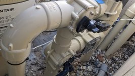
I suspect that the check valve in the pic is part of your make-up water for the spas' overflow but can't tell for sure. See if you can shut off the valve in the lower left of the pic, so that water can't go to the check valve. If you can, then as a test, shut off the pump and shut off that valve and see if the spa still drains down. If it does not, then the check valve is not working.

Thanks,

Jim R.
 
That is the makeup check valve. This piping section is right after the SWG. The water come out of the SWG and through the valve oriented horizontally just in view at the top right of center. You can see it represented in my layout sketch. I can see some filter media in the check valve, so I image that the valve is not closing fully.
 
  • Like
Reactions: Jimrahbe
Thread Status
Hello , This thread has been inactive for over 60 days. New postings here are unlikely to be seen or responded to by other members. For better visibility, consider Starting A New Thread.