Install Help: Pentair iChlor/Intellichlor retrofit to EasyTouch8 (elect & plumbing)

LgHorn

0
Nov 21, 2016
41
Cedar Park, TX
Hi all - I am converting to a SWCG and per the advice from the great folks on this site I am staying with Pentair due to the automation and remote capabilities possible integrating with my existing ET controller w/ScreenLogic2. I have an iChlor SWCG with the additional Intellichlor power center on the way arriving tomorrow and have questions regarding the install if I go the DIY route (which I've been told is fairly straight forward, both plumbing and electrical). The only hesitancy I have with a DIY install is if I could possibly qualify for the extended warranty with Pentair by having a pro install the SWCG along with a new filter, MPV, and valve actuator (all Pentair). Not sure if the MPV and actuator qualify as an additional (3rd) piece of equipment for that purpose.

If I do install myself, I searched TFP and Google for installation steps, pictures/videos, specifically for integrating with an existing ET system. I imagine some exist, but I could not find what I am looking for in the weeds, and most online videos show connecting the power center to a standard timer box.

Questions:
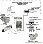
  1. Beyond the manual (which I've read) is there a published schematic, photos, or steps to hook up the power center to an existing ET including connectivity of the communication cable (RS-485) when I believe there is already one connected from my IntelliFlo VS pump to the ET comm input.
  2. Related to above, if there is only 1 comm input on the standard ET8 system, will I need to pigtail the two RS-485 cables or is there enough room to connect both sets of cables into the same comm port?
  3. Other than an additional copper wire and screw nut for bonding to my system, are there any other parts I need to pick up from the store to complete the electrical install of the power center such as to wire the power from the ET pump relay to the Intellichlor power center? If so, what type and gauge wire? Do I get a few feet of each from the hardware store? Presume I'll want some flexible conduit and male/female ends to connect to each box.
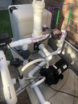
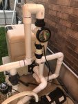
  4. Plumbing: my existing plumbing is attached below with a couple of options I've come up with so far. I do not see much value/point in Opt 1 as there will be no need for the tab feeder (and thus the check valve). I have marked both options up with a vertical install as that is what is recommended in Pentair's manual for "optimal performance" of the cell. Otherwise I would go with a straight horizontal install assuming I have sufficient room for a 12" straight pipe prior to the cell and before the "T" to my returns, but alas I don't think I'd have room. The valve on the vertical line after the tab feeder is my spa return line which will be having an actuator installed so I can control my spillway. Any alternative suggestions or concerns with the plumbing plan as depicted?
I am hopeful I can knock this out in a few hours this weekend and get to generating chlorine. I did a partial drain yesterday to lower the CYA, CH and working to lower TA (from 100), and plan to add salt this week so everything is ready to go. Tab feeder is off and bleach only until the SWCG is installed and working as expected.

Thanks!
 

Attachments

  • ichlor_install.jpg
    ichlor_install.jpg
    529.2 KB · Views: 60
I will take a shot at some of it -- Jim will be back to correct my errors :mrgreen:

1. All I have seen is the manual and the inside of the door of the ET. It has a schematic. The RS 485 connects to the Com Port. I believe you can piggyback them -- but please have Jim confirm.
2. See above
3. 12-14 AWG. 8 gauge bonding wire. Length depends on how close your mounting your IC power center. You will need to enter the ET box at the bottom.
4. Cannot the spa make up line (T after tab thing) go away? You can program a Spillway function that will rotate your existing actuated return valve to direct to pool or spa. That would give you plenty of room to install horizontally. I know Pentair says vertical, that is so the flow switch will fail open (hopefully) due to gravity.

Don't buy or cut anything until Jim checks my statements!!

Take care.
 
  • Like
Reactions: LgHorn
Lg,

Here ya go.. Pretty much the same thing as the manual already shows.. Except I just noticed in my old SWCG manual they actually have an error where they have the SWCG wired to the line side of the pump filter relay instead of the load side.. oops!!!

110177


Marty has you covered...

You can force all the wires into the same connector or you can wire-nut or solder all the wires together with a jumper to the com port.. Just make sure the colors and numbers all match.

The com wire going to the IntelliFlo has nothing to do with the Power center other than it is connected to the same J20 com port.. There is only one com port..

The 12" before the cell is a good idea but not carved in stone.. I have about an inch.. Or I should say my pool builder installed it with about an inch.. Seems to work fine. the closer to 12" the better but I would go crazy over it.

Note that this is for a 220 volt connection to the power center.

Let us know if you have any questions.

Thanks,

Jim R.
 
  • Like
Reactions: LgHorn
Lg,

Here ya go.. Pretty much the same thing as the manual already shows.. Except I just noticed in my old SWCG manual they actually have an error where they have the SWCG wired to the line side of the pump filter relay instead of the load side.. oops!!!

View attachment 110177


Marty has you covered...

You can force all the wires into the same connector or you can wire-nut or solder all the wires together with a jumper to the com port.. Just make sure the colors and numbers all match.

The com wire going to the IntelliFlo has nothing to do with the Power center other than it is connected to the same J20 com port.. There is only one com port..

The 12" before the cell is a good idea but not carved in stone.. I have about an inch.. Or I should say my pool builder installed it with about an inch.. Seems to work fine. the closer to 12" the better but I would go crazy over it.

Note that this is for a 220 volt connection to the power center.

Let us know if you have any questions.

Thanks,

Jim R.
@Jimrahbe - thanks a lot! This helps - the manual is just a bit hard for me to read legibly and understand. I’ll check to confirm if any wires are included in the kit other than what’s connected and contained inside. Appears I may need to get the wiring for the power from the ET pump relay, a 4 wire for the J20 com port and some wire nuts, and a copper bonding wire.

Thanks also for the info on spacing the cell. I’ll take some measurements along with the cut-out from the kit and see what I have to work with.

@mknauss - thanks for your input, info and suggestions. Very helpful! Regarding the spa return, you’re right - I’m sure that could be taken out of the picture and I could just run either pool or spa, but I do like having the option to run the spillway when the pool is on as a “feature” or just to chlorinate the spa at some portion of time during the pool run time. I bought the actuator at the same time as the SWCG from Polytec so will install it to another aux relay.

Thanks again gents! If I have any other questions I’ll be sure to ask, and will let you know how the install goes.

Nate
 
If you took out the spa make up, you can still run the spa as a 'feature' and circulate it every day. That is what Spillway function is for. It draws water from the pool and sends it to the spa.
 
Nate,

What you don't seem to understand is that the EasyTouch has a built in function called "Spillway" that does the same thing as the make up line that Marty recommends removing.
Basically you can have it run fast when you want to refresh the spa water, and slow when you just want to show off for your guests, or you can have it off most of the time to reduce you pH increase...

If you have automation, you do not need the manual make up system...

Thanks,

Jim R.
 
  • Like
Reactions: LgHorn
Nate,

What you don't seem to understand is that the EasyTouch has a built in function called "Spillway" that does the same thing as the make up line that Marty recommends removing.
Basically you can have it run fast when you want to refresh the spa water, and slow when you just want to show off for your guests, or you can have it off most of the time to reduce you pH increase...

If you have automation, you do not need the manual make up system...

Thanks,

Jim R.

Ah, OK...I see what you guys mean. And I’ve seen the function “Spillway” on the ET but it does nothing on mine (that button goes pool or spa and that’s it).

So if I were to remove the make up line, how would I configure the spillway function, especially with multiple speed options? And if I remove it, would I just cut the pipe and cap it off? Another disappointment in my pool builder - they installed the automation, but plumbed the make up line and didn’t configure the spillway.

Thanks,
Nate
 
Have yet to hear of a pool builder that understands automation.

You have Screenlogic --- so Jim knows the easy way to set it up. I can do the Easytouch way ----
 
  • Like
Reactions: LgHorn
Nate,

You can add the Spillway function and try it out before you cut out the make up valve...

Using Screenlogic go your circuit sets up page like the one below...

View media item 1964
Select a Feature circuit that is not being used and Name it "Spillway".. and then set the Function to "Spillway". You can have the Icon show up on whatever page you select in the lower right of the page..

Select another Feature circuit and name it "High Speed" and set the Function to "Generic"

Then go this pump speed set up page...


Find an empty line and add "Spillway" and a low RPM like 1000 or maybe 1200

Find an empty line and add "High Speed" and a high RPM like 3000...

For this to work, your system has to have an automated Intake valve that selects if the pump is sucking water from the Pool or the Spa.. And and automated Return valve the sends water back to the Pool or the Spa..

Assuming you have those two valves, which any pool/spa should have, then here is how it works.

In ScreenLogic, push the icon that says "Spillway".. The valves should turn to suck water from the Pool and send the water to the Spa at 1000 RPM.. If the pump was already on and running faster than 1000 RPM you will have to turn off whatever is running the pump at the faster RPM..

Then pushing the "High Speed" icon will cause the pump to ramp us to 3000. Pushing the "high speed button again will cause the pump to return to 1000 RPM. Pushing the Spillway icon again will turn off the spillway...

Once you test it to make sure it works, then we can talk about scheduling it...

Thanks,

Jim R.
 
  • Like
Reactions: LgHorn

Enjoying this content?

Support TFP with a donation.

Give Support
Nate,

Keep in mind the whole point here is to normally run with the spillover off.. If your plan is to run the spillover most of the time, then it would be best to leave the make up valve.

The reason for this is that when in the automated spillover mode all of the water is being returned to the pool via the spa.. This is fine for a couple of hours, but you really don't want to run it this way all the time, because you will have no flow out of your normal pool return eyeballs.

Thanks,

Jim R.
 
  • Like
Reactions: LgHorn
Nate,

Keep in mind the whole point here is to normally run with the spillover off.. If your plan is to run the spillover most of the time, then it would be best to leave the make up valve.

The reason for this is that when in the automated spillover mode all of the water is being returned to the pool via the spa.. This is fine for a couple of hours, but you really don't want to run it this way all the time, because you will have no flow out of your normal pool return eyeballs.

Thanks,

Jim R.
Jim - yes, that's exactly what I'm looking to do and why I bought the actuator for the make up valve - have it shut off most of the time and only turn it on for one of these two purposes: (1) refresh/circulate/chlorinate the spa on a daily schedule, (2) run as a feature on rare occasions.

I tested the new circuits/features and it works exactly as expected with the make up valve closed. So, both use cases above can be achieved by using the Spillway I now have set up and the make up line could be removed. The only reason I could see to consider keeping it is not out of necessity, but only if I have a desire to run the spillover as a feature WITH the pool circulation running at the same time. This is how it's been running for the last 3 years with the make up valve open, and I ordered the actuator so I could have it off most of the time and only turn it on when I wanted the "feature". The only possible disadvantage, per se, is not having the option to run the "feature" while the pool circuit is also running.

On an aside, I also noticed your Intelliflo VS circuits and speeds and was interested to test something similar out. To date I've been running my pump 10 hrs/day on a set medium speed (~2100 RPM) as that's what my pool requires to get any real skimming action. It runs at a higher speed 2 hrs/day for the suction side cleaner schedule. Today I lowered the pool circuit speed to 1250 RPM and added in a Low Skim (1500) and High Skim (2100). At the low pool circ speed I get zero surface movement including in the skimmers, turned on Low Skim and still saw no skimming action. I may play with it to find the bare min speed to get some surface movement. My pool is surrounded by crepe myrtles so without skimming for a good portion of the day there's lots of surface debris and time for leaves to sink to the floor. I would prefer to run my pump at a lower speed for the majority of the day, so it may be some trial and error with various scheduled speeds to find a decent balance. Of course after I install the SWCG I'll have to also determine what my min speed is to achieve adequate flow to the cell, so that may change things up a bit.

And strangely, as of yesterday, I noticed I now have air in my lines and on the top of the pump well. I've stopped and started multiple times, opened up the relief valve on the filter when priming, etc., but air remains. And now I've digressed further from the topic of this thread.

Thanks,
Nate
 
Last edited:
Nate,

Your really do not need much surface motion to have good skimming.. Watching it is not a good way to judge how well it is working.

Throw in 5 ping pong balls or something else that floats... Run the pump at 1200 or so and come back in an hours and see where they are. If they are all in the skimmers, then you are good. If not try running at 1500... or ???

Keep in mind that I do not have a heater which makes it possible for me to run at a lower RPM...

Some of my pics are really out of date, and some of my circuits are there only because of what I do here at TFP, and are not used on my pool... So, just because you see it does not mean I use it, or that is necessarily a good idea... :mrgreen:

I currently only run three speeds.. 1250 most of the time, 1500 a couple times a day for an hour, and 2800 for my waterfall, once a day for 15 minutes.

Thanks,

Jim R.
 
  • Like
Reactions: LgHorn
@Jimrahbe @mknauss Thank you both for your advice, information and details - definitely helped my install go without incident! Spent 3 hours this afternoon and everything seems to be working properly. No leaks either for my first endeavor in PVC plumbing work! :LOL:

I decided to leave the spa make up line in - it’s turned off and not hurting anything, and I’d prefer to have the option to use it as/when desired. Have yet to decide to install the actuator on the make up or main drain (to have closed the majority of time to increase skimmer suction, but open on a schedule).

The iChlor is showing low salt, reading 2900, although my Taylor test kit came out at a “perfect” 3400. I added another 40 lb bag of salt so hopefully that will be sufficient. I can already taste it in the water.

Thanks again gentlemen for your help and knowledge! :cheers:
 

Attachments

  • F2C4C765-ECF9-43EF-9663-A0AC0C790F0F.jpeg
    F2C4C765-ECF9-43EF-9663-A0AC0C790F0F.jpeg
    347.3 KB · Views: 29
  • A8E98CD0-A6A4-485E-B9EC-9140C1592095.jpeg
    A8E98CD0-A6A4-485E-B9EC-9140C1592095.jpeg
    532.5 KB · Views: 28
Lg,

Here ya go.. Pretty much the same thing as the manual already shows.. Except I just noticed in my old SWCG manual they actually have an error where they have the SWCG wired to the line side of the pump filter relay instead of the load side.. oops!!!

View attachment 110177


Marty has you covered...

You can force all the wires into the same connector or you can wire-nut or solder all the wires together with a jumper to the com port.. Just make sure the colors and numbers all match.

The com wire going to the IntelliFlo has nothing to do with the Power center other than it is connected to the same J20 com port.. There is only one com port..

The 12" before the cell is a good idea but not carved in stone.. I have about an inch.. Or I should say my pool builder installed it with about an inch.. Seems to work fine. the closer to 12" the better but I would go crazy over it.

Note that this is for a 220 volt connection to the power center.

Let us know if you have any questions.

Thanks,

Jim R.
Installing mine now...I was scratching my head looking at the manual which shows the transformer wires going to the line side of the pump filter relay. I could not figure out the purpose...but now that you pointed out it is an error, I can move forward and connect to the load side of the relay. THANK YOU JIM! I know this shows as inactive thread...but it was very helpful to me!
 

Attachments

  • Picture1.png
    Picture1.png
    130.4 KB · Views: 5
  • Like
Reactions: Jimrahbe
Installing mine now...I was scratching my head looking at the manual which shows the transformer wires going to the line side of the pump filter relay. I could not figure out the purpose...but now that you pointed out it is an error, I can move forward and connect to the load side of the relay. THANK YOU JIM! I know this shows as inactive thread...but it was very helpful to me!
btw...the j20 com wiring in the manual is incorrect also...shows 2 wires instead of 4 like your diagram.
 
Thread Status
Hello , This thread has been inactive for over 60 days. New postings here are unlikely to be seen or responded to by other members. For better visibility, consider Starting A New Thread.