IC40 - Sanity Check on 120V Wiring

ThatHuskyGuy

Member
Mar 20, 2021
7
Travelers Rest, SC
Pool Size
25000
Surface
Vinyl
Chlorine
Salt Water Generator
SWG Type
Pentair Intellichlor IC-40
Hello all,

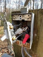
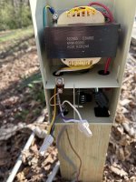
I am in the process of converting to a SWG and am at the wiring stage of the IC40+PC100. I'm scratching my head a bit wondering if I'm missing something obvious with the wiring.

Here's what I have:
  • 120V at the pool subpanel
  • Single pole switch controls my pump, so I am tying the PC100 into that
  • At the switch, I added a pigtail for hot and tied the neutrals + grounds together
  • At the PC100, I followed the diagram and tied yellow+black to hot and white+violet to neutral

Here's what happens (no IC40 hookup yet--only the PC100 is connected):
  • Upon first fire up yesterday, the transformer was humming loudly and within a minute fried the internal 10A fuse and then tripped the breaker
  • I replaced the fuse, left the cover open (to try to get some live multi/clamp readings), and it trips the breaker immediately now before it has a chance to fry the fuse
  • I disconnected the PC100 so only the pump was connected, and it runs fine without issue for extended periods. It ran fine while the PC100 fried the fuse yesterday, too. This leads me to believe the issue is with the wiring at the PC100.

Pictures and a poor hand-drawn diagram are attached. I am typically pretty good at simple electrical circuits, but this one has me scratching my head. Am I overlooking something simple?

Thank you for any help/guidance!
 

Attachments

  • PC100 Schematic.JPG
    PC100 Schematic.JPG
    468.2 KB · Views: 29
  • Poor Diagram.JPG
    Poor Diagram.JPG
    310 KB · Views: 27
  • Switch Wiring.JPG
    Switch Wiring.JPG
    708.5 KB · Views: 23
  • PC100 Wiring.JPG
    PC100 Wiring.JPG
    383.9 KB · Views: 26
THG,

You should not connect your neutral to the bare copper ground.

Does the old wiring to switch actually have a neutral wire?

I see three cables going into the switch box. Please tell me where each cable comes from.

The problem I see right now is once the transformer is fried, it is fried. :(

Do you have a voltmeter? If so, disconnect the transformer wires from the new power cable. Then measure the AC input you are trying to use to power the transformer.

Let us know what you find.

Thanks,

Jim R.
 
Hi Jim,

Thank you for the quick reply!

Sorry if my pictures or schematic weren't clear--there isn't a neutral connected to ground. (unless I'm blatantly missing something) The neutrals are connected together and the grounds are connected together. Which picture makes you say don't connect neutral to ground?

To answer your questions:
  • The old wiring to switch does have a neutral (it's 12/3 UF-B, so hot, neutral, ground)
  • Picture added with clarification on the three cables entering the switch box
  • 120V to power the transformer

I appreciate the input and guidance here. If I fried it then it's my fault and I'll have to buy a new one, but I want to make sure the wiring is correct before hooking up a new one. Hopefully the color coded picture makes more sense...if not please let me know.
 

Attachments

  • 120V.JPG
    120V.JPG
    454.8 KB · Views: 13
  • Color Coded.jpg
    Color Coded.jpg
    570.2 KB · Views: 13
  • Disconnected.JPG
    Disconnected.JPG
    322.4 KB · Views: 13
THG,

Sorry, I must have just misread your post about the neutral and ground. I doubt that would cause your issue anyway..

If you have 120 volts going into the transformer, as your meter shows, then it should work. Your wiring connections to the transformer looked good to me.

If this were my system, I'd disconnect the transformer from the surge card and then measure the transformer's secondary output. Should be about 28 volts AC. If that is good, then most likely you have a bad surge card.

Thanks,

Jim R.
 
@Jimrahbe - It acts like a short circuit as soon as it's reconnected, so I'm unable to test the transformer's output while powered. I disconnected the output leads from the surge card (with the intention of measuring them), but as soon as I wired it back up and turned on the switch the transformer popped. (so I suspect it may have blown this time)

@JamesW -
  • Black to White = 0V (same voltage so they zero out)
  • Black to Ground = 120V
  • White to Ground = 120V


The pump still works fine. This may be TMI, but I verified that the leads going into the PC100 have the same behaviors as the leads going into the pump:
  • Both black and white measure 120V when breaker is on, regardless of switch position (circuit is closed via the switch)
  • There is no continuity between black/line side of switch or white/line side of switch until the switch is turned on (ie - switch is working properly to close the circuit)
  • Black/white have continuity between them
  • There is no continuity between black/ground or white/ground (ie - no short)
 
Last edited:
It sounds to me like you have a 240V line, not a 120V line.

Show us pics of your pump and pump motor data plate.
 
This site says the Pentair SUPERFLO SF-N2-1A you have in your signature is a 230V pump....


1678137741402.png
 

Enjoying this content?

Support TFP with a donation.

Give Support
@JamesW @ajw22 @Jimrahbe

You guys just gave me the click moment I needed. I do in fact have 240V here. Somehow I got it stuck in my head that I had 120V at the switch, and that assumption was never revisited.

ajw22 the pump tag confirms it. As does my double pole breaker.

Where do I find the facepalm emoji? Looks like I screwed the pooch on such a simple part of this. Not a cheap lesson to learn.

Appreciate the help!
 
You have a 2-speed 240 volt pump.

It looks like your black and white lines are the switched leg and your wiring is mixed up.

How do you switch from high speed to low speed?

1678138089578.png
 
You need to take a total look at the wiring for the pump from the breaker through the light switch to the pump.

It is against code to switch one leg of a 240V circuit for safety reasons. Someone working on the circuit can assume there is no power to either wire when one leg is hot. You should be using a double pole switch to turn both legs on or off.

In addition the wire color coding is against code and a white wire should not have been used on a 240V circuit without it being remarked. It can lead someone astray as it did you.

Is the pump 240V CB GFCI as required by current code?
 
It's a two-speed pump with a common and two switched legs.

So, you should have three wires to the pump (4 including the ground) or a switch on the pump.

You need to figure out which wire is common and which legs are the switched legs.

How is the pump switched from high to low?
 
@JamesW - Pump speed is controlled with the toggle switch on the pump itself.

@ajw22 - I did not realize this but makes sense now why I assumed a few things. Since I likely have to replace the transformer due to my negligence, I will do my due diligence in swapping out the wires and switch for the equipment.

We moved in a couple years ago and have found quite a few “homeowner specials”, especially when it comes to electrical work. (120v wiring for under cabinet lights spliced with twisting the wire and electrical tape buried behind walls) Sounds like this setup is another one to add to the pile. Granted, I should have done my due diligence and not made some of the assumptions that I did.
 
Last edited:
The wiring still does not make sense.

You should be getting 240 line to line.

If you get two timers like a T104 and a T106, then that will control the pump On/Off and the switching of high speed to low speed.

You would connect the SWG to the two red dots (Terminal 2 and 4 of the T104 timer).

1678139052685.png
 
The wiring still does not make sense.

You should be getting 240 line to line.

If you get two timers like a T104 and a T106, then that will control the pump On/Off and the switching of high speed to low speed.

You would connect the SWG to the two red dots (Terminal 2 and 4 of the T104 timer).


Sorry to make you scratch your head this time! This is another issue caused by my incorrect assumptions, and I suspect the original 0 was because I measured with the switch off. (so I was still getting 120V per side, which made me think it was on)

I went out and remeasured. With everything powered on and hooked up as 240V (temporarily), I get 240V from line to line at the PC100.
 
  • Like
Reactions: JamesW and Jimrahbe

Enjoying this content?

Support TFP with a donation.

Give Support
Thread Status
Hello , This thread has been inactive for over 60 days. New postings here are unlikely to be seen or responded to by other members. For better visibility, consider Starting A New Thread.