How do you remove motor from Hayward SP2300VSP Max-Flo VS pump?

e1836936

Well-known member
Apr 20, 2013
97
Florida
Hello all,

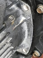
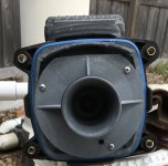
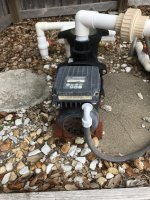
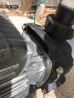
By hand, I’ve been trying to remove the dead motor from my Hayward SP2300VSP Max-Flo VS pump, do I can replace it but I’m not making any progress.

I removed the four 9/16 bolts that attach it to the pump but when I try to pull it off it just wiggles ever so slightly. I even attempted to gently pry it out with several different size flathead screwdrivers but that’s not working either; it’s actually starting to damage the plastic a bit on the pump.

What would you do?

3790E623-5A5F-455F-A24D-975BEA813794.jpegE53B5DB1-1B8F-4002-BDA4-093511D75349.jpegE2B4DBD8-436F-4A32-B335-11C7F9832272.jpeg
 
Hello all,

By hand, I’ve been trying to remove the dead motor from my Hayward SP2300VSP Max-Flo VS pump, do I can replace it but I’m not making any progress.

I removed the four 9/16 bolts that attach it to the pump but when I try to pull it off it just wiggles ever so slightly. I even attempted to gently pry it out with several different size flathead screwdrivers but that’s not working either; it’s actually starting to damage the plastic a bit on the pump.

What would you do?

View attachment 484128View attachment 484129View attachment 484130
You have to open the entire pump (the other 4 bolts), remove the impeller (5/16" Allen wrench in fan-end of motor to hold the shaft), then the sealplate will come off the motor.
 
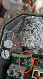
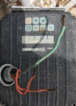
🤔 Looks like I’ve had 2 orange (I assume hot) wires & 1 green (I assume ground) going in, but only 1 hot wire is connected to L1 and the other is connected to nothing, so L2 was empty.View attachment 484149
An awful lot of water got into that area. The pump would never have run with only one wire connected. The second power line probably came loose when the motor was moved.
 
An awful lot of water got into that area. The pump would never have run with only one wire connected. The second power line probably came loose when the motor was moved.
I have that pump and have been very happy with it for years. Hopefully it is just the reconnecting the L2 (and as much cleanup as possible) and your up and working.

I’ve had it for about 10 years, but it hasn’t been running properly for several months now. It’s been stuck on “PR 4” and I’ve unable to change any settings on the panel. It’s been just barely moving water, but enough so that if I kept on 24/7 it would kinda keep the water looking good. I just haven’t been able to vacuum during that time. The motor actually stopped running completely this past week, so I bought a Century VGreen 165 VS motor, which I’m attempting to replace it with.

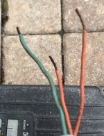
That 2nd hot wire might’ve come off when the motor was removed as it’s much shorter than the other.

.99007B21-4211-40F3-91DB-87386BAB96B9.jpeg
 
Last edited:
I’ve had it for about 10 years, but it hasn’t been running properly for several months now. It’s been stuck on “PR 4” and I’ve unable to change any settings on the panel. It’s been just barely moving water, but enough so that if I kept on 24/7 it would kinda keep the water looking good. I just haven’t been able to vacuum during that time.

That 2nd hot wire might’ve come off when the motor was removed but it’s much shorter than the other. The motor actually stopped running completely this past week, so I bought a Century VGreen 165 VS motor, which I’m attempting to replace it with.

.View attachment 484162
Ah.. I imagined that this could have been a "new to you" situation, but you have quite a bit of history with this one. Mine isn't 10 years, but you might be showing me what might be eventually in my future. Good luck!
 
  • Like
Reactions: e1836936

Enjoying this content?

Support TFP with a donation.

Give Support
I’ve had it for about 10 years, but it hasn’t been running properly for several months now. It’s been stuck on “PR 4”, and just barely moving water, but enough so that if I kept on 24/7 it would kinda keep the water looking good. I just haven’t been able to vacuum during that time.

That 2nd hot wire might’ve come off when the motor was removed but TBH, the motor actually stopped running completely this past week, so I bought a Century VGreen 165 VS motor, which I’m attempting to replace it with.
V-Green ECM165SQU (control panel, no longer made) or EVQ165 (single button)? You're going to need a time clock for either to have better control over the filtration times. Your Max-Flo had both a timer and time clock. The 165 V-Greens have only a timer that starts a filter cycle when power is applied.
Just did the ECM165SQU (last one available at any of my suppliers) on the same pump about a month ago for a long time customer who has that same pump (that I installed 10-12 years ago) and the same issue, water in the control area. Works well. If you still have a time clock from when your pump was installed, it should work.
I got the ECM165SQU and I do have a time clock; but never new the Max-Flo had one. 😊
 
So here’s where I’m at with the dead Max-Flo. Am I correct to assume the first piece I’m looking at is the diffuser and it should be removed first, before I remove the impeller?

Also, should the diffuser just pop off or do I have to remove those 3 screws first?
B608A887-7480-4478-9B9E-15B82DC446EA.jpeg


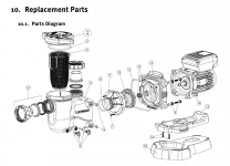
9. Shaft Seal Change Instructions IMPORTANT SAFETY INSTRUCTIONS PLEASE READ AND FOLLOW ALL INSTRUCTIONS When servicing electrical equipment, basic safety precautions should always be observed including the following. Failure to follow instructions may result in injury.  WARNING – To reduce risk of injury, do not permit children to use this product.  Disconnect all electrical power service to pump before beginning shaft seal replacement.  Only qualified personnel should attempt rotary seal replacement. Contact your local authorized Hayward Dealer or service center if you have any questions. Exercise extreme care in handling both the rotating and the stationary sections of the two-part replacement seal. Foreign matter or improper handling will easily scratch the graphite and ceramic sealing surfaces. 9.1. Removing the Motor Assembly 1. Remove the four (4) 5/16" x1.75" hex head bolts, which hold the motor assembly to the pump/strainer housing, using a 1/2" wrench or socket. 2. Slide the motor assembly out of the pump/strainer housing, exposing the diffuser. Remove the three(3) diffuser screws and pull the diffuser off the seal plate to expose the impeller. 9.2. Removing the Impeller 3. To prevent the motor shaft from turning, secure using a 6mm hex wrench on the motor shaft through the fan shroud on the back of the pump. 4. Remove the impeller by rotating counterclockwise. 9.3. Removing the Ceramic Seat 5. Remove the spring seal assembly and seal plate from the motor by removing the four (4) 3/8” x 1” bolts that secure it to the motor, using a 9/16" wrench or socket. 6. Press the ceramic seat with rubber cup out of the seal plate. If tight, use a small screwdriver to tap seal out. STOP - Clean all recesses & parts to be reassembled. Inspect gaskets & replace if necessary. 9.4. Seal Installation 7. Clean and lightly lubricate the motor shaft and seal recesses in the seal plate with a dilute solution of nongranulated liquid-type soap. Gently wipe the polished face of the ceramic seal with a soft cotton cloth. Lubricate the rubber cup on the ceramic seat and press it firmly into the recess of the seal plate, with the polished ceramic surface facing out. 8. Reassemble the motor to the seal plate using the four (4) 3/8” x 1” bolts. Torque the bolts to 100 in-lbs. 9. Gently wipe the black, polished surface of the spring seal assembly with a soft cotton cloth. 10. Press the spring seal assembly onto the motor shaft, with the black polished surface facing the ceramic seat. 9.5. Replacing the Impeller and Diffuser 11. Screw the impeller onto the motor shaft in a clockwise direction. Tighten snugly by holding motor shaft with wrench as noted in step #3. 12. Place the diffuser over the impeller and onto the seal plate, aligning the three (3) protruding pins with the matching holes in the seal plate. Note: Flat side of diffuser rim will face up. Replace the three (3) diffuser screws, Torque screws to 20 in-lbs.
 
  • Like
Reactions: e1836936
Yes.

Yes.


9. Shaft Seal Change Instructions IMPORTANT SAFETY INSTRUCTIONS PLEASE READ AND FOLLOW ALL INSTRUCTIONS When servicing electrical equipment, basic safety precautions should always be observed including the following. Failure to follow instructions may result in injury.  WARNING – To reduce risk of injury, do not permit children to use this product.  Disconnect all electrical power service to pump before beginning shaft seal replacement.  Only qualified personnel should attempt rotary seal replacement. Contact your local authorized Hayward Dealer or service center if you have any questions. Exercise extreme care in handling both the rotating and the stationary sections of the two-part replacement seal. Foreign matter or improper handling will easily scratch the graphite and ceramic sealing surfaces. 9.1. Removing the Motor Assembly 1. Remove the four (4) 5/16" x1.75" hex head bolts, which hold the motor assembly to the pump/strainer housing, using a 1/2" wrench or socket. 2. Slide the motor assembly out of the pump/strainer housing, exposing the diffuser. Remove the three(3) diffuser screws and pull the diffuser off the seal plate to expose the impeller. 9.2. Removing the Impeller 3. To prevent the motor shaft from turning, secure using a 6mm hex wrench on the motor shaft through the fan shroud on the back of the pump. 4. Remove the impeller by rotating counterclockwise. 9.3. Removing the Ceramic Seat 5. Remove the spring seal assembly and seal plate from the motor by removing the four (4) 3/8” x 1” bolts that secure it to the motor, using a 9/16" wrench or socket. 6. Press the ceramic seat with rubber cup out of the seal plate. If tight, use a small screwdriver to tap seal out. STOP - Clean all recesses & parts to be reassembled. Inspect gaskets & replace if necessary. 9.4. Seal Installation 7. Clean and lightly lubricate the motor shaft and seal recesses in the seal plate with a dilute solution of nongranulated liquid-type soap. Gently wipe the polished face of the ceramic seal with a soft cotton cloth. Lubricate the rubber cup on the ceramic seat and press it firmly into the recess of the seal plate, with the polished ceramic surface facing out. 8. Reassemble the motor to the seal plate using the four (4) 3/8” x 1” bolts. Torque the bolts to 100 in-lbs. 9. Gently wipe the black, polished surface of the spring seal assembly with a soft cotton cloth. 10. Press the spring seal assembly onto the motor shaft, with the black polished surface facing the ceramic seat. 9.5. Replacing the Impeller and Diffuser 11. Screw the impeller onto the motor shaft in a clockwise direction. Tighten snugly by holding motor shaft with wrench as noted in step #3. 12. Place the diffuser over the impeller and onto the seal plate, aligning the three (3) protruding pins with the matching holes in the seal plate. Note: Flat side of diffuser rim will face up. Replace the three (3) diffuser screws, Torque screws to 20 in-lbs.
Thanks...That's very helpful!

Even though they're replacing a different Hayward motor, what are your thoughts on this video as I guide to install the VGreen?
 
Thanks!

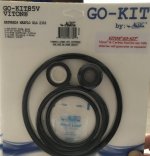
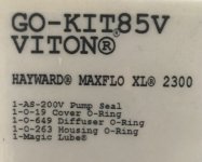
Yes, from my previous research and guidance here on the aforementioned thread, I believe that I'm wanting to replace the following seals, o-rings & gaskets (OEM part #s in parenthesis), and I believe the GO-KIT85V that I purchased has aftermarket replacements for.

Two-piece shaft seal (SPX2700SA)
Diffuser o-ring (SX220Z2)
Housing gasket (GMX600F)
Strainer cover o-ring (SPX2300Z4)

I'm not sure which of these, if any, are the "body O ring", to which 1poolman1 referred.
 

Enjoying this content?

Support TFP with a donation.

Give Support
Thread Status
Hello , This thread has been inactive for over 60 days. New postings here are unlikely to be seen or responded to by other members. For better visibility, consider Starting A New Thread.