Help me understand how my EasyTouch automation is wired

Dec 28, 2015
32
San Diego, CA
Hi All, my goal is to be able to install low voltage landscape lighting and a stenner pump for chlorine. I’m fairly comfortable with circuit wiring, but I need help getting oriented to how things are wired up currently.

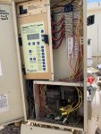
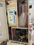
The pool appears to have had a Compool to EasyTouch upgrade. Even though the motherboard supports 8 relays, am I correct in believing there are only four relays in the box and that all are currently in use?

There is an Intelliflow VS 3050 pump, a Purex Triton WhisperFlow spa pump, a pool light, a spa light, and a Purex Triton Minimax heater.

How do I know what these relays control?
8B3841DF-11B4-4111-A23D-604607A45D46.jpeg

And if I want to install low voltage landscape lighting and a stenner pump, will I need to buy two 20amp GFCI circuit breakers and two relay assemblies? (Or is there something in the existing setup I can tie into?)

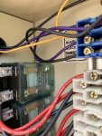
Do I need to buy the same Compool/Midtex relays, or can I put in newer Pentair relays alongside the old ones?
07F83EAB-B76E-443A-8261-8371CEE9D6A0.jpeg

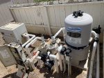
Finally, I have four actuator valves. (See photo.) One switches between skimmers and cleaner. I’m not sure what the second one does — maybe switches to main drain? One sends water up to the solar. And one is after the heater, I assume for isolating return to spa vs pool+spa? What do you think?

Would all the actuators be connected directly to 24v feature circuits on the motherboard?
007E3BEC-8ABF-485A-ACD6-BCF74CDF712E.jpeg

Thanks for your help in making sense of what’s what!
 
Last edited:
Your actuator left to right are:
  • Pool/Spa Return
  • Pool/Spa suction
  • Cleaner
  • Solar
Yes, you only have four high voltage relays in your ET/Compool system.

I don't know what it takes to add more high voltage relays at this time. Maybe @ogdento @Pool Clown or @kadavis may know.
 
Are your two lights separately controlled?

The first relay is your filter/pump relay. With a VS pump being continuously powered it is not connected to it. You would have other devices you want to turn on and off with the pump connected to it, like a SWG.
 
Yes, the pool light and spa light are separately controlled.

No SWG. The VS pump does have its timing & speed controlled through the EasyTouch. But if I'm understanding correctly, you're saying that the VS pump just has a control wire from the EasyTouch motherboard, but no power from a relay (because it's powered separately).

So I could use that open relay for turning a stenner pump or the lighting transformer on and off, which achieves one of the goals.
 
The first white wiring block is empty, the second is wired for 120V, the third is 120V, and the fourth is 240V. You have to look deeper into the wiring to see what buttons each relay is plugged into.
 
You could use the Filter/Pump relay to power the Stenner. That relay is only powered when the pump is running.
 

Enjoying this content?

Support TFP with a donation.

Give Support
@Jimrahbe
Hope you don't mind me summoning you. You seem like the guy to ask about EasyTouch wiring. Do you have any thoughts on what kind of relays I should get if I want to add 2 more to my Compool-to-EasyTouch upgrade (see photos in original post)? Should I stick with the old Compool/Midtex relays and wiring harnesses so that everything fits neatly in the box?

Also, in terms of wiring things up, should I get two separate 15A GFCI breakers and wire each one to the line input of a relay?

Thanks!
 
@aasarava

I don't know squat about ComPool, but If I had your system, I would go out of my way to buy the Compool relays and the little white connector blocks.. For me it would be worth the expense to have them mount correctly.

If you have room in the breaker box, I would use two GFCI breakers.. One would go to an external outlet, where you could plug in your Stenner. The other could also go to an external outlet for your landscape lights, or you could wire it direct if that makes more sense. You could just use one breaker, but then when it popped, you would not know which circuit had the issue..

I don't fully understand the labels on your control pad but "assume" the following:

Pump/Filter relay is not being used.. Using... Terminal Block #1 -top
Aux 1 (Spa Lights) turns on the Spa light. Using Terminal Block #2 (120 Volts)
Aux 2 (Cleaner) does not use a relay and just moves a valve. No Terminal Block
Aux 3 (Jets) turns on the single speed pump #2 Using Terminal Block #4 (240 volts)
Aux 4 (Pool Lights) turns on the Pool lights. Using Terminal Block #3 (120 volts)

Thanks,

Jim R.
 
Ok, turns out I need more help than I thought. Maybe it's that I'm just not understanding how things are wired, but it looks to me like multiple contractors over the years cut corners.

First, I don't see any GFCI breakers in the subpanel. (And the main panel feeding the circuit to the pool equipment also does not use a GFCI.)

There is, hower, a GFCI courtesy receptacle. It looks to me like someone has pigtailed the load conductor from the receptacle to the two conductors from the pool & spa lights and then fed that into a standard circuit breaker. So, first question: Is this allowed?

I tried swapping a Siemens GFCI breaker into the spot where the standard circuit breaker is but the GFCI breaker would not let me switch it on. Is this because of the GFCI receptacle that is upstream?

Next, it looks like the conductors for the pool lights are coming through the same conduit up into the subpanel. How is that possible? I thought each light (spa & pool) would have its own separate set of conductors, especially since the lights are on opposite sides of the pool.

Here's what I'm thinking of doing to clean things up and add a level of safety. How does this look?
1. Use the standard single pole 15A circuit breaker to power the GFCI courtesy receptacle.
2. Add a single pole 15A GFCI breaker (wired through two relays) for the pool & spa lights. Would use a pigtail to the two conductors for the lights.
3. Add a new single pole 15A GFCI breaker (wired through a relay) to power the low voltage lighting transformer that I'll be adding.
4. Replace both 2-pole 15A standard breakers for the pool pump and spa pump with 2-pole 15A GFCI circuit breakers.
5. Eventually when I'm ready for the Stenner pump, add another 15A GFCI for that.

Final, most important question: Am I asking for trouble by re-doing everything? Should I just leave it alone?

Thanks!

8B3841DF-11B4-4111-A23D-604607A45D46.jpeg
 
A,

It is a pretty common practice to use a GFCI outlet as the GFCI for the pool lights..

In the old days, pumps did not require a GFCI breakers.. I suspect there are millions of them still out there.

I suspect the you wired your new GFCI breaker wrong and that is why it did not work.. But that is just a guess.. :mrgreen:

Thanks,

Jim R.
 
  • Like
Reactions: aasarava
Thread Status
Hello , This thread has been inactive for over 60 days. New postings here are unlikely to be seen or responded to by other members. For better visibility, consider Starting A New Thread.