Help ID and replacement of Aqua Rite SWG model and board

mick1putt

0
Silver Supporter
Mar 15, 2014
65
Raleigh, NC
Pool Size
33000
Surface
Vinyl
Chlorine
Salt Water Generator
SWG Type
Hayward Aqua Rite (T-15)
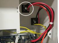
My Aqua Rite SWG (installed June 2008) started acting funny at the end of last year - inconsistent diagnostic readings, flashing numbers, wouldn't generate chlorine. I'm trying to open the pool this year, assuming I'm going to have to repair or replace the circuit board, but I'm getting constant "no flow" indicator. I removed the flow sensor, and can't see anything wrong with it. I held contacts together but still got the "no flow" from panel. Do I need to replace the flow sensor or is this part of the problem with the board?

I removed the board, and assume the burn on back indicates a problem, and guess I need to replace it, but I'm having trouble ID-ing exactly what model I have and what board. Pictures of the board are current the panel pic is old - not indicating check salt now.

I looked at similar post by Derek77, and mknauss suggestion to start with this Hayward Aqualogic - Further Reading page, but my board doesn't look like any of these.

How do I proceed with troubleshooting and/or replacement of the board?

6C43BA5D-AFF8-43DD-85D2-4B9010712E7A_1_105_c.jpegB5C0D2FA-EC86-4A60-87CC-9D578CEC72EB_1_105_c.jpegEE6C80BE-70F8-4BEE-87C0-7F2D91B70A94_1_105_c.jpeg
 
You need a Hayward GLX-PCB-RITE board. You have an older Goldline board from before Hayward bought Goldlibe.

The burnt solder point is at the K-1 relay and causing your problems. Your board may be repairable. B&L Enterprises will repair Hayward boards if you are not comfortable doing board level repairs
 
Thanks ajw22, I wouldn't mind trying the repair myself, but after looking at B&L Enterprises site, that option seems best. I'll get it shipped off today!
 
For the Hayward Aquarite, the replacement mainboard is called GLX-PCB-RITE. I am guessing what you have is the older rev 1.40
Should you wish to replace the mainboard, the newest r1.59 would be a better choice.
You can fix the board if you can solder. If not, send it out for repair but do not expect it will solve the "No Flow" issue.
The flow switch is similar to a light switch, either on or off. Get an old telephone cord and twist together the wires on one end. Disconnect the cell and power on the board. Plug in the hacked tel cord to the board.
The no flow led should blink and then off. Disconnect the tel cord, the no flow led should lit steadily. If this is true, the no flow circuitry on the board is operational.
 
And I see some head discoloration on the back of the board where the thermistor is.., That is the big black quarter looking component. If you never replaced it, it may be the next widget to go...see here:
Correct and it needs some fresh solder. The main problem is the K1 post not making contact with the solder pad and K2 is also about to go. If it were me, I would clean the post, use wire wrapping techniques, scrape off the trace coat farther away and establish a good contact between the post and the trace pads.
Most board repair services out there always assumed Thermistor replacement (easy money, eh). If their ads says they don't accept r1.59 or r 1.47 then you know their ability is limited to the thermistor issue.
Just recently, a distant neighbor sent out his trol r1.47 for repair. They did shotgun the thermistor and charged him $80 only to get ****** when he found out the board wasn't fixed. The board would not power on and it turned out one of the chip is bad.
 
Thanks everyone, you can always count on TFP for help.

Yes it's rev 1.40, and the solder at the thermistor is a replacement I did a few years ago. I didn't know I could replace with a newer version, in fact that's why I wanted to have it repaired, to be sure it was compatible.

I may have jumped the gun, but I've already sent it to B&L Enterprises for repair, I hope he is reputable. He only charges $49.99, so it just didn't make sense for me to repair it, but now I'm wondering about the price, and if all he does is replace the thermistor and send it back. His website looks legit, he says he tests every unit before returning it.


"The flow switch is similar to a light switch, either on or off. Get an old telephone cord and twist together the wires on one end. Disconnect the cell and power on the board. Plug in the hacked tel cord to the board."

What about when I took the flow sensor out and held contact together? Shouldn't that have closed the circuit and turned off the no flow light?
 
I may have jumped the gun, but I've already sent it to B&L Enterprises for repair, I hope he is reputable. He only charges $49.99, so it just didn't make sense for me to repair it, but now I'm wondering about the price, and if all he does is replace the thermistor and send it back. His website looks legit, he says he tests every unit before returning it.
Competitors forced them to slashed down their cost to repair. Your thermistor looks good but it will make sense for them to replace it to survive the promised warranty. However, they "might" claim your pcb is badly burned or damaged beyond economical repair. So just be prepared if in case they offer you an alternative like uncollected pcb for a fraction.
What about when I took the flow sensor out and held contact together? Shouldn't that have closed the circuit and turned off the no flow light?
Correct! But what if it did not work as expected? Would you be suspecting the flow switch or the controller? The hacked tel cord approach will help rule out one or the other at a glance.
 
I heard back from B&L Enterprises, he says he's fixed my board, but a bad rectifier caused the burn and he's afraid it will happen again, suggests replacing both rectifiers. I don't even know what the rectifiers are ;)??? I'll search TFP and find out.
 

Enjoying this content?

Support TFP with a donation.

Give Support
but a bad rectifier caused the burn and he's afraid it will happen again, suggests replacing both rectifiers.
Not true.

The rectifiers that carry any current are not even on the circuit board.

The big, current carrying rectifiers are mounted in the box behind the circuit board in the upper right and look like this.

pcb-red-and-blk-cable.jpg


2807-18.jpg


One burn is on one leg of one of the relays. Relay part number Omron G8P-1C4P 24VDC. The relay carries about 6 to 8 amps and that's why the solder melted.

The other burn mark is on one leg of the thermistor. Part number SL322R025.

The thermistor also carries 6 to 8 amps.

The burn marks are not due to a bad rectifier.


Last edited:
Ask them to send you a picture of the rectifiers that they want to replace and ask how much it would cost.

If they are talking about the big rectifiers mounted in the box, how are they determining that they are bad?

What's their hypothesis about how the rectifiers caused the problem?

There's no reason to believe that the rectifiers are bad or that they caused the burn marks.
 
  • Like
Reactions: duade and mguzzy
That's baloney! Wonder if B&L have ever gotten away with this trick to upsell their customers the bridge rects. Good for you, TFP has your back!
As JamesW said, for the Aquarite the two bridge rectifiers are mounted in the metal enclosure as shown in the above pic. The failure mode of those high current rects is usually "shorted". And if any one of those rects is shorted, the yellow 20 amp fuse mounted on your pcb is guaranteed to blow instantly.
Kindly ask them if they will keep the promised warranty if you declined buying the rects.
 
The failure mode of those high current rects is usually "shorted". And if any one of those rects is shorted, the yellow 20 amp fuse mounted on your pcb is guaranteed to blow instantly.
If the rectifiers fail, what exactly happens?

Where would any current go?

Wouldn't the damage be limited to the rectifiers?
 
Even if you didn't have the rectifiers and you put AC voltage from the transformer to the cell, I don't think that you would get high amps.

The board shuts off at 8 amps in any case.

Maybe if AC is sent down to the cell, it could be an issue, but there's no reason to believe that the rectifiers had anything to do with the problems.

The thermistor is a known problem and the relay leg solder points are known problems.

I am not aware of any issues related to the rectifiers.

If they fail, you would usually just lose power downstream.

Rectifiers and transformers rarely fail.
 
For the aquarite, the 24V AC from the x'former output travels to the bridge rects via the 20 amp fuse mounted on the pcb. Therefore, without the pcb or if the 20 amp fuse is missing the rects are off.

Edit: I dld the below diagram from here. Add some labels for clarification.
AQR x'former + Rects.jpg
 
Last edited:
  • Like
Reactions: JamesW
Wow, you guys and TFP are amazing. Unfortunately, or maybe not, I acted before getting all of this info. This is my pool, that I've managed since installation, but I'm renting the house now, and was only in town for a few days trying to help my renters get the pool up for the season, so I had to act fast.

Sorry for the delay but here's an update.

The electronics are way over my head, but I can follow instructions, and have handled most repairs myself. I've done some soldering (built a stereo amp and pre-amp from a kit a few years ago), and as I mentioned above replaced the thermistor on this board in 2014. In this case I was in a hurry, the price was right, and the recommendation to use B&L came from a long time TFP contributor (thanks ajw22).

I don't know about the rectifiers actually being a problem, but I do think B&L is legit, he communicated with me and explained what and where the rectifiers are. He sold me two rectifiers, since we could not be sure which was bad, for $30, and repaired my board for $55, and did it in one day.

Here is his email telling me he thought a rectifier was bad.

" I Have your board repaired but I have one concern. You have at least 1 bad rectifier which caused the board to burn on the relay. It will damage the board again and most likely the cell as well. I can not warranty the repair unless you replace the rectifier set. I sell these for $35.00 a set if you want to include a new color coded set with the shipment of your board. I can invoice you for the additional amount due.
If you elect not to replace the rectifiers I would not expect the board to last for more than 90 days. Please advise as to how you want to proceed."

My renter has installed the repaired board and the rectifiers, but he's still getting the "No Flow" readout, and he can't determine if the repaired board is going to work until we get the "No Flow" problem fixed. I was hoping that was somehow related to the board, but apparently not. I've asked him to splice the flow sensor wires together to see if the light goes out, and I don't understand why holding the contacts together didn't turn off the "No Flow" indicator. If I was there I'd tinker with it (with the help of TFP) and figure it out, but in this case convenience and expedience takes priority. I think I'm going to order a new flow sensor.

the next question is do I buy the Hayward flow sensor (is it GLX-FLO-RP?) or a "compatible" aftermarket flow sensor? This time I'll wait for replies :salut:
 
the next question is do I buy the Hayward flow sensor (is it GLX-FLO-RP?) or a "compatible" aftermarket flow sensor?

I buy genuine parts. Mixing in third party parts of questionable quality just complicates debugging. I find the time wasted is not worth any money saved.
 
  • Like
Reactions: mick1putt

Enjoying this content?

Support TFP with a donation.

Give Support
Thread Status
Hello , This thread has been inactive for over 60 days. New postings here are unlikely to be seen or responded to by other members. For better visibility, consider Starting A New Thread.