Hayward MaxFlo VS 500 new install won’t power on

twokgrad

Member
Oct 16, 2024
10
Florida
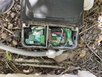
I was recently flooded by Hurricane Helene so I searched high and low to get a direct replacement for my Hayward MaxFlo VS 500 pump. Got it today, wired it up just like the one that was flooded - dip switches all set to 0, automation control set black to 2, yellow to 3 and gray to 4 and of course the power and grounds connected. In the original the grey conduit from the display dead ended into the 1/2/3/4 block and was left loose inside the cover by the equipment installer with apparently no issues. So we just wire nutted each of those four lines individually.


When I flip the breaker, there is live power to the unit on both the incoming wires and the wires inside the unit. The Hayward automation turns on and even says that the pump is turned on. However the display does not light up (I don’t recall if the original pump ever lit up as I usually only looked at the automation). There is also a red light emitting from the COM side of the enclosure - just a steady red light.

Any idea how to get my pump to actually pump?
 
Welcome to TFP.

In the original the grey conduit from the display dead ended into the 1/2/3/4 block and was left loose inside the cover by the equipment installer with apparently no issues. So we just wire nutted each of those four lines individually.

The display must be disconnected when the pump is connected to automation.

What did you wire nut together?

Post pictures of your pump wiring.

1729153746780.png
 
Last edited:
Thank you!

The picture with the wire nuts is the new pump wiring and the other picture is the original pump wiring.

One other thing to note - currently we are without internet so I’m not sure if that is impacting the ability of the automation system. It still has the right date and time though.

2nd note - we originally had all 5 dip switches to Off but changed 1 to On to see if that would make a difference, which it did not.
 

Attachments

  • IMG_5263.jpeg
    IMG_5263.jpeg
    529.4 KB · Views: 6
  • IMG_4960.jpeg
    IMG_4960.jpeg
    660.5 KB · Views: 6
Last edited:
When I read the instructions above it references “2nd terminal block”. Does that mean I need to remove the original block in this new pump and replace it with the one RS485 block that was provided?

I had assumed both blocks were identical.
 
When I read the instructions above it references “2nd terminal block”. Does that mean I need to remove the original block in this new pump and replace it with the one RS485 block that was provided?

I had assumed both blocks were identical.
The two RS-485 blocks are identical. Using two blocks makes it easier switching between automation and local display control.

Did you run the pump with the local display to confirm it worked?

Which Hayward automation system do you have?

Did the automation see the new pump HUA and did you change the configuration for the new pump?
 
No I didn’t run the pump with just local display first - we hooked it up directly to automation.

Attached is my automation system currently powered off.

I’m not sure on the HUA as that is beyond my current understanding 😊
How would I test or confirm that?
 

Attachments

  • image.jpg
    image.jpg
    444 KB · Views: 3
That looks like an OmiHub system.

You should connect the display wires to the other terminal block, switch the control blocks, and run the pump locally and confirm it works with no leaks.

Then change the pump back to the automation connection and setup the pump in the Omni Configuration.

See page 49 in https://hayward.com/media/akeneo_connector/asset_files/1/0/1008757_RevA_60ee.pdf

You need to edit the Configuration, Select Bodies of Water, Select Filter Pump, and the system should give you a list of the HUA it sees for the new pump and you select it. The HUA label is on the middle divider between the power side and low voltage side.

img_2091-jpeg.602601


1729170949395.png
 
If you find your Configuration screen is password protected try the MSP ID number.
 

Enjoying this content?

Support TFP with a donation.

Give Support
That looks like an OmiHub system.

You should connect the display wires to the other terminal block, switch the control blocks, and run the pump locally and confirm it works with no leaks.

Then change the pump back to the automation connection and setup the pump in the Omni Configuration.

See page 49 in https://hayward.com/media/akeneo_connector/asset_files/1/0/1008757_RevA_60ee.pdf

You need to edit the Configuration, Select Bodies of Water, Select Filter Pump, and the system should give you a list of the HUA it sees for the new pump and you select it. The HUA label is on the middle divider between the power side and low voltage side.

img_2091-jpeg.602601


View attachment 614697
One quick question - when I hook up the display to the block, what should the Dip switches be set to?
 
One quick question - when I hook up the display to the block, what should the Dip switches be set to?
What were the dip switches when you got the pump with the display connected?
 
Quick update - hooked up the display mentioned. The pool is still in bad shape after the hurricane so I’m going to Kermit running as is without the automation until the water is cleared up. Then I will follow through on the HUA.

Thank you again!
 
Quick update - hooked up the display mentioned. The pool is still in bad shape after the hurricane so I’m going to Kermit running as is without the automation until the water is cleared up. Then I will follow through on the HUA.

Thank you again!
Probably the best thing to do.

Check back in here when you are ready to connect it to your OmniHUb.
 

Enjoying this content?

Support TFP with a donation.

Give Support
Thread Status
Hello , This thread has been inactive for over 60 days. New postings here are unlikely to be seen or responded to by other members. For better visibility, consider Starting A New Thread.