Drew,

I am not sure pushing the "F" button by itself will start the pump.. For the pump to run several things have to happen..

You have to have at least one Circuit linked to a speed.. As in Pool = 1500 RPM
Then the Circuit has to be scheduled to run..
And the Circuit has to be on..
You can't be in the Service mode.
The correct pump type must be selected in the EasyTouch

If all these things have been satisficed, then the pump should run.. Keep in mind it might take a few seconds to a minute for it to start.

While it is possible that the pump's controller may be bad, just based upon past experience here at TFP, it is more likely that the new board is just not fully set up..

I would connect just the pump to J20.. Make sure all the above items are for sure set up correctly and see what happens.

*** Another thought.. We have see the pins on the control cable corrode on both the cable side as well as the pump side, so I'd inspect those.

I would leave ScreenLogic disconnected from the RS-485 bus until you can get the pump running..

Good luck,

Jim R.
 
> Thanks very much. I'm thinking the VS drive is the more important piece to replace at this point. Screenlogic is a nice-to-have.

Given the testing you have described where the light circuits are not triggering I would say that the pump is getting comms and is most likely not your problem. I have a pretty good understanding of how Pentair communicates with that pump and the fact that it sends the proper packets to the pump tells me that one side of the comms are working and the other is not. In this case the thing that tells the pump to disable the control panel is [255, 0, 255][165, 0, 96, 16, 4, 1][255][2, 25] in decimal for pump at address #1. The pump is probably responding with [255, 0, 255][165, 0, 16, 96, 4, 1][255][2, 25] but EasyTouch can't hear it.

This same scenario plays out when ScreenLogic sends a message to ET to flip the relay for an aux circuit. My guess EasyTouch isn't hearing that either.
Off to the replacement races - Is the RS-485 chip in the pump drive or the keypad? Makes a big difference in cost.

Drew
 
There is an RS-485 chip in the motherboard, the pump, chlorinator, and in the ScreenLogic controller. However, the one we are worried about is the one that is acting as the master. This exists on the ET motherboard. We already know that the pump is getting commands from it since it has a Display Not Active. ET will send that message I described earlier every few seconds to indicate that the pump is connected to automation and the ET controller is in charge. The other thing that you mentioned was that your chlorinator lights came on. Some of these lights will illuminate because the the power is wired to the filter relay. For now let's ignore the chlorinator though because it doesn't really start giving up indications until it senses flow and doesn't allow you to change the setpoint.

Now all that being said, you mentioned you get crickets from the controller whenever you turn on a light from ScreenLogic but the circuit status' show correctly in ScreenLogic. To be sure is that correct? If that is the case do the test I outlined with the voltmeter if you have one. Let's eliminate the the wiring since you are using indoor rated category cable to connect your ScreenLogic to the OCP (ET motherboard). Remove all the wiring from the comm port and test the voltage between the rightmost pin and pin 2 (result: 1.5 - 2.0vdc) & 3 (result: ~3vdc). This will tell us whether there is power differential on the pins. Then check the voltage between pin #2 & 3 (D+/D-). This voltage should be around 2.1 to 3.3 volts on the average voltmeter. If all these are correct our next focus will be on the wiring.

Do you by chance have another controller other than ScreenLogic? If you do, we will be able to see the quality of the comms on the date displayed on that controller. If the time and date are wrong it is because the communications are not being received by the controller. However, I think ScreenLogic uses an NTP server to get its time not the time inside the controller.
 
Quick Update:

I was able to connect an rs-485 adapter to the output of the ET main board and verify there's data coming off of J20 +/- terminals. I connected to the output of the Screenlogic protocol adapter and saw nothing, same with the Intelliflo VS. The iChlor however, worked fine - good data. I connected it back to J20 and was able to change the salt chlorination levels for the pool and spa from the ET and have see the changes on the iChlor screen. That let's me know that both the VS drive and the Screenlogic need replacing. Looked online SunPlay has the drive for around $800, Screenlogic adapter for $450. Aren't pools fun? :)
 
Well it looks like you have some techie prowess. Did you examine the messages coming off the bus? I pretty much know what is coming off ET but if you are up to it and have a spare Raspberry Pi laying around we can determine whether either of these components are even attempting to communicate.


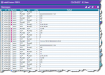
This should allow you to see the output from each piece of equipment. The output below is the communication between an IntelliCenter and two separate IntelliFlo VS pumps. Note the Action 4 messages the OCP sends a request to each pump to disable its control panel and the pump echo's it back saying OK.
The other bits of information are the same for all Pentair controllers.
Action 1 sets the current speed
Action 6 sets the drive state (turns the pump on/off) 10 = on, 4 = 0ff.
Action 7 requests the current status (watts, rpm, error codes)

This can also show you all the requests from ScreenLogic, IntelliChlor, or any other traffic on the RS485 bus.
1614965191009.png
 
Thread Status
Hello , This thread has been inactive for over 60 days. New postings here are unlikely to be seen or responded to by other members. For better visibility, consider Starting A New Thread.