I have a brand new system that I can't for the life of me get to work. The installation guy couldn't figure it out so now it has defaulted to me.
Problem:
-Due to supply shortage I purchased the newest pump model Intelliflo3 which supports direct communication via. Bluetooth or Wifi. The pump works fine when operating in this mode however I have also installed the Easytouch PL4/PSL4 to have one central controller.
The problem is now I have to control Heater, Valves, sensors etc... via the ET with the ScreenLogic application and I have to control the pump with the Pentair Home application.
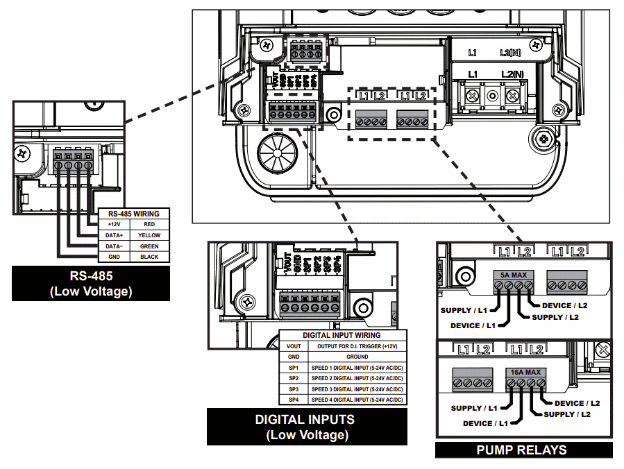
As such I have installed the RS-485 communication wire between the ET and the pump. I only have the two communication lines plugged in on both sides as instructed in the manual (Green and Yellow wire). My understanding is that the pump should go into automation mode when connected in this manner, the Magenta/Pink 'Connect LED' should light up but I have yet to get this color light up.
When you use the ET to configure the connection to the pump and specify the VSF pump if you check the status it says 'NO COMM'. Obviously the ET is not communicating to the pump. I have verified the address is set to 1 on the pump. What is odd is if I tell the ET to stop the pool it will stop the pump, without powering it down. I say this because the install guy setup the pump through the Relay-1 circuit but I read it shouldn't be setup this way for this pump.
My understanding is that the pump should be connected directly to the Circuit Breaker not the relay for this type of pump. Now after a period of time the relay will turn off the pump but again this is a separate issue. What I can't get to work is to get the pump to turn on via the ET interface.
I am now at a complete loss. I have no Idea what else the problem could be. Am I missing something?
Any help would be greatly appreciated.
Thanks,
Aaron
Problem:
-Due to supply shortage I purchased the newest pump model Intelliflo3 which supports direct communication via. Bluetooth or Wifi. The pump works fine when operating in this mode however I have also installed the Easytouch PL4/PSL4 to have one central controller.
The problem is now I have to control Heater, Valves, sensors etc... via the ET with the ScreenLogic application and I have to control the pump with the Pentair Home application.
As such I have installed the RS-485 communication wire between the ET and the pump. I only have the two communication lines plugged in on both sides as instructed in the manual (Green and Yellow wire). My understanding is that the pump should go into automation mode when connected in this manner, the Magenta/Pink 'Connect LED' should light up but I have yet to get this color light up.
When you use the ET to configure the connection to the pump and specify the VSF pump if you check the status it says 'NO COMM'. Obviously the ET is not communicating to the pump. I have verified the address is set to 1 on the pump. What is odd is if I tell the ET to stop the pool it will stop the pump, without powering it down. I say this because the install guy setup the pump through the Relay-1 circuit but I read it shouldn't be setup this way for this pump.
My understanding is that the pump should be connected directly to the Circuit Breaker not the relay for this type of pump. Now after a period of time the relay will turn off the pump but again this is a separate issue. What I can't get to work is to get the pump to turn on via the ET interface.
I am now at a complete loss. I have no Idea what else the problem could be. Am I missing something?
Any help would be greatly appreciated.
Thanks,
Aaron
Last edited by a moderator: