- Oct 1, 2022
- 814
- Pool Size
- 20000
- Surface
- Plaster
- Chlorine
- Salt Water Generator
- SWG Type
- Hayward Aqua Rite (T-15)
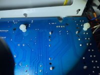
So I failed at disengaging the gears of the actuator because my locking knob is nowhere to be found.Sorry what toggle switch are we referring to?