Bad install = burned SWG power center

postscripto

Member
Sep 5, 2023
18
Phelan CA
Pool Size
29200
Surface
Plaster
Chlorine
Salt Water Generator
Hello all, so my Jacuzzi JSCS40 SWG Power control center burned down a few days ago.
I noticed that the power was off, so I checked and the fuse at the bottom of the unit had tripped so I reset it and turned it on again to see a little puff of smoke come out the back of the unit. 💀
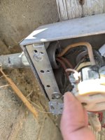
I immediately turned it off and started investigating. The first thing I noticed is that it wasn't grounded! the second thing was that the unit is shipped wired for 220v and the unit was connected to a 120v receptacle. so it must have been under performing this whole time which definitely put some stress on the circuits. LAST but not least! The receptacle is 15A. The power module is rated 2.2A @ 220V and 4.4A @ 120V so if the unit is running while the pump motor is on quick clean mode (RPM = 3450) then the Internal Meter reads 2330 Watts. That means that quick clean mode is already almost 20A so more reasons for it all to fail.
Oh! and of course the receptacle was not even GFCI!! Complete FAIL

Right now I'm looking to replace the Power Module for a Breeze 540 I found on Craigslist but I want to make sure I don't make the same mistakes as my installer, who surprisingly is not replying to my messages.

So first I was going to replace the receptacle and add a WR GFCI 15A. I don't have the money for a full upgrade into 20A right now so I wanted to see if I can make it work with 15A
I lowered the Quick Clean setting on the Pentair VST to 2775 which would keep it around 1000w and therefore 10A.
Then I need to open it and make sure its wired for 120v and last I will install an 8ft grounding rod to ground the unit.

I feel like this would prevent it from happening again! Any thought?

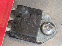
I also bought some S4065K semiconductors to solder back into the faulty unit to see if I can save it!
 

Attachments

  • fried_circuit.jpg
    fried_circuit.jpg
    478.3 KB · Views: 26
  • fried_circuit2.jpg
    fried_circuit2.jpg
    299.6 KB · Views: 26
  • cracked semiconductor.jpg
    cracked semiconductor.jpg
    355.8 KB · Views: 25
  • 120:220wiring.jpg
    120:220wiring.jpg
    442.8 KB · Views: 23
  • ground.jpg
    ground.jpg
    319.7 KB · Views: 25
You do not connect pool equipment to 8 foot grounding rods.

What makes you think that equipment was not properly grounded?

Are you concerned with bonding, not grounding?


Your SWG failed due to being wired for 240V when connected to 120V. Lack of bonding did not cause any failure. And your pump being connected to a 15A circuit while pulling more then that did not cause the SWG failure. You have multiple installation problems.

When was your pool built? An inground pool should not have a Pentair Superflow VST pump connected to a 120V outlet. Show us the electrical wiring for your pool?
 
Last edited:
Hi and thanks for your reply. The house/pool was built in 1959. It had very old equipment including a single speed pump and a fiberglass sand filter.
I paid a local pool installer to upgrade the equipment to what you can see in my signature and to add a skimmer since it didn't even have one!
I also sealed off all the cast iron pipes and added PVC so I can switch to Salt, which I did.

Looks like the installer did it all wrong, at least the electrical side of it.

Regarding the grounding rod, it is instructed in the manual:
Ground with an 8AWG bonding wire from the lug (Image 2) on the bottom of the Control Center to a grounding rod (thisis necessary to protect the integrity of the electronic systems).
Screenshot 2024-09-30 at 11.58.36 AM.pngground.jpg
There is a grounding lug at the bottom of the unit not connected to anything.

I do agree that the 220v wiring is what ended u messing up the circuit and cracking the semiconductors. But opening things up was like opening a can of worms...
I'm not home now but I'm attaching some photos I had on my phone that show some of the setup. Both the pump and the Power center are connected to the electrical box on the side.
I was gonna open it up once I receive the GFCI receptacle I ordered.
Let me know if this answers your questions and thanks again.
 

Attachments

  • PXL_20240930_185526589b.jpg
    PXL_20240930_185526589b.jpg
    827.3 KB · Views: 86
  • PXL_20240930_185552324.jpg
    PXL_20240930_185552324.jpg
    653.1 KB · Views: 18
  • PXL_20240930_185540290.jpg
    PXL_20240930_185540290.jpg
    695.1 KB · Views: 19
Regarding the grounding rod, it is instructed in the manual:

View attachment 612170View attachment 612171
There is a grounding lug at the bottom of the unit not connected to anything.

I will tell you the manual is incorrect and goes against the NEC.

I suggest you check with a licensed electrician before you do connect to a grounding rod.

The NEC requires a house structure at the Main Service Panel to have a single ground point that all circuits connect to. Multiple grounds will cause ground loops in your house electrical service.
 
And while that electrician is out there, verify that the pump is actually wired for 110. I highly suspect that it is actually 220. Just because there are two convenience outlets doesn't mean that everything in and out of the box is 110. What is going on in the main breaker box for that equipment? There may even be a GFCI breaker in the box there. But it most assuredly is time for a pro to look it over - so call that electrician.
 
That Intelliflo pump is unlikely to be running on 120V. You have more going on in that electical box that contains the 2 gang 120-V outlet and a switch.

What does the switch control?

Are your pump CBs GFCI?

pxl_20240930_185526589b-jpg.612174
 
I'll try to reply to all of you in one message...!

You probably have a bonding wire on the pump motor that you can extend to this so no ground rod is needed. If not then is any part of the equipment or pool bonded?

No bonding that I see except the 2 anchors going into the brick wall. There is a metal plate at the back of the unit but its not bonded to anything outside of itself.

The NEC requires a house structure at the Main Service Panel to have a single ground point that all circuits connect to. Multiple grounds will cause ground loops in your house electrical service.

That's another down the line problem about bringing a late 50's home to code. There is no single ground rod connected to the main panel.
I'm actually hoping to restore the whole panel after I fix my septic tank! Looks like I will have to hire an electrician. I was hoping to try to do the pool side of it myself.

And while that electrician is out there, verify that the pump is actually wired for 110. I highly suspect that it is actually 220. Just because there are two convenience outlets doesn't mean that everything in and out of the box is 110. What is going on in the main breaker box for that equipment? There may even be a GFCI breaker in the box there. But it most assuredly is time for a pro to look it over - so call that electrician.

I'm quoting from the Pentair manual "the SuperFlo VST pump has a dependable and robust Totally Enclosed Fan Cooled motor and can adapt to 115V to 230V and 50hz or 60hz power with no special wiring or switching" I'll open up the box but the outlets are definitely 120v. The circuit breaker at the panel is for 20A though.

That Intelliflo pump is unlikely to be running on 120V. You have more going on in that electical box that contains the 2 gang 120-V outlet and a switch.
What does the switch control?
Are your pump CBs GFCI?

The switch controls the outlets and the CB is not GFCI. It was wired to a timer by the main panel and then into a 20A breaker.
 
IMG_0687.jpeg
Is the black cable what was powering the JSCS40? Are you sure the two courtesy outlets don’t have the duplex tab broken, and are actually being fed by two separate 120v circuits? Then you would actually have 240v available in the junction box which the pump and the JSCS40 could be powered by.
 
That Intelliflo pump is unlikely to be running on 120V. You have more going on in that electical box that contains the 2 gang 120-V outlet and a switch.

What does the switch control?

Are your pump CBs GFCI?

pxl_20240930_185526589b-jpg.612174
Directly from the Pentair site:

The SuperFlo VST Variable Speed Pool Pump features sophisticated technology in a simple to operate pump. Designed for pool owners who are practical and like to save, the SuperFlo VST pump has a dependable and robust Totally Enclosed Fan Cooled motor and can adapt to 115V to 230V and 50hz or 60hz power with no special wiring or switching.
 

Enjoying this content?

Support TFP with a donation.

Give Support
Is the black cable what was powering the JSCS40? Are you sure the two courtesy outlets don’t have the duplex tab broken, and are actually being fed by two separate 120v circuits? Then you would actually have 240v available in the junction box which the pump and the JSCS40 could be powered by.

Yeah the lower black one was powering the JSCS40 and the upper one is the pump. I will open it up and take a look. Is there a quick way to check for that? Checking voltage between the two hot wires? That should add up to 220v?
 
  • Like
Reactions: Mdragger88
Yeah the lower black one was powering the JSCS40 and the upper one is the pump. I will open it up and take a look. Is there a quick way to check for that? Checking voltage between the two hot wires? That should add up to 220v?
It’s not always that simple. Look at the outlet, are there separate wires feeding each outlet on the brass colored screw side? Is the tab in the middle of the outlet broken off or removed? Perhaps pull the cover and shoot some pictures of how the pump and JSCS40 is wired.
 
That Intelliflo pump is unlikely to be running on 120V. You have more going on in that electical box that contains the 2 gang 120-V outlet and a switch.
It’s not always that simple. Look at the outlet, are there separate wires feeding each outlet on the brass colored screw side? Is the tab in the middle of the outlet broken off or removed? Perhaps pull the cover and shoot some pictures of how the pump and JSCS40 is wired.

You were right! I opened it up and surely the 2 outlets are regular 120v but the switch (which controls power to both the pump and the SWG) is 240v. There are 2 red wires going in and then a black and a white one going into both the Pump and the SWG. The receptacle and switch are both grounded to the box. I'm adding the photos I took.

So if both the Pentair VST and the Jacuzzi JSCS40 were both 240v what caused the SWG to burn? 🤔

switch.jpg
 

Attachments

  • powertowall.jpg
    powertowall.jpg
    376.3 KB · Views: 14
  • 2240cableSWG.jpg
    2240cableSWG.jpg
    391 KB · Views: 14
  • 240in.jpg
    240in.jpg
    343.6 KB · Views: 14
  • 120outlet.jpg
    120outlet.jpg
    318.1 KB · Views: 14
The power module is rated 2.2A @ 220V and 4.4A @ 120V so if the unit is running while the pump motor is on quick clean mode (RPM = 3450) then the Internal Meter reads 2330 Watts.
Back of the napkin math says both the VSP and SWG combined were drawing a total 11.9A on an assumed 20A circuit.
o if both the Pentair VST and the Jacuzzi JSCS40 were both 240v what caused the SWG to burn?
Any corroded connections feeding the SWG? Admittedly I’m not much help here as to why it burned. How old is the power module?
 
Are you positive the SWCG is wire correctly inside the box to actually be 240?
There does look to be copper exposed on the bottom of the board - so that might be the short that tripped the fuse. Or due to age, the S4065K just failed.
 
  • Like
Reactions: Mdragger88
Back of the napkin math says both the VSP and SWG combined were drawing a total 11.9A on an assumed 20A circuit.
Any corroded connections feeding the SWG? Admittedly I’m not much help here as to why it burned. How old is the power module?
Yeah your napkin math is correct! Running at 240v changes everything. The outlets are still 120v that's what confused me, but the switch is definitely 240v.
I might exchange the switch for a 20A GFCI outlet. Not sure I can find a switch with GFCI... I am assuming it's 20A since the breaker is 20A. I should check the wire gauge.
I can't see any corroded connections. The power module is from 2021 and was installed that same year. That's only 3 years to burn down...
I found a Breeze 540 which is the same exact unit from a different brand. I wanted to replace it but I just want to make sure it doesn't burn down again!
Are you positive the SWCG is wire correctly inside the box to actually be 240?
There does look to be copper exposed on the bottom of the board - so that might be the short that tripped the fuse. Or due to age, the S4065K just failed.
Looks fine. The copper is the ground and it connects the switch to the outlet to the SWG.
The only thing is that both the JSCS40 Power center and the Pump are not bonding to anything. Both bonding lugs are exposed and clearly not used.
Where do you see the copper exposed on the bottom of the board? I bought 4 S4065K's and will try to solder them back in to see if I can salvage the power center but I will be installing the Breeze 540 in the next few days. First thing is GFCI and then I'll look into bonding it all...

Thanks so much! This is def helping me troubleshoot this mess.
 
So after digging in, the receptacle has a 120v outlet and a 240v switch. Not sure how to turn the switch into a GFCI so I might just add a 240v outlet... which is a bit confusing to have a 120 and a 240 next to each other! Other than that I assume it's all 20A since the breaker is 20A. I need to measure the gauge.

I just got the used Breeze 540 (which is also made by CMP) and wanted to replace it but I'm afraid I don't really know the reason why it burned so it might happen again!
The Breeze is 6 years old and my Jacuzzi only lasted 3 years... so yeah I still can't tell why it fried.. oh well... I'm going to switch to GFCI and cross my finders.

The only think that is the bonding... the pump and the SWG are still not bonded to anything :( but I don't think that was the reason
 
So after digging in, the receptacle has a 120v outlet and a 240v switch.
What is the switch controlling?

The only think that is the bonding... the pump and the SWG are still not bonded to anything :( but I don't think that was the reason
The lack of bonding had no bearing on the Breeze burning out.
 

Enjoying this content?

Support TFP with a donation.

Give Support
Thread Status
Hello , This thread has been inactive for over 60 days. New postings here are unlikely to be seen or responded to by other members. For better visibility, consider Starting A New Thread.