AUX2 relay is always getting power

rajthepilot

Active member
Jul 13, 2022
28
Indianapolis, Indiana, USA
I have four relays with my Aqua Logic Salt system (Left to right - Pump, Lights, Aux 1 and Aux 2). I was trying to check how much voltage they receive and if it is AC or DC If I check for AC current, the Pump relay gets about 42 AC, and AUX 2 gets about 38 AC. If I check DC, then they're close to 19 DC (I wasn't hoping to see numbers for AC and DC)

While checking, something happened to Aux2 relay, I heard a click (which means it connected). Now it is always powered. The board continually sends out 38 AC or 19 DC (don't know which one), even if I turn off AUX2.

Can anyone tell me why that's happening? I have a Aqua Logic circuit board.
 
All of the newer high voltage relays used by Jandy, Hayward, Pentair are nominally 24vdc and are completely interchangeable. They are Omron G7L-2A-BUBJ-CB-DC24

I would check your programming in the Aqualogic and the circuit board.
 
First of all check the AUX2 button on your panel and make sure it is not stuck on. It is a stuck button, programming in the Aquaplus, or a bad board.

Post pics of your Aquaplus panel open showing the wiring.
 
Can you disconnect one if the lv conductors on the relay? If the relay still allows power to pass line to load then the relay is likely bad.
 
what is an Iv conductor? I checked the back of the board as well, Aux 2 is always powered when the board has power. There are no issues with any solder connections in the back of the circuit board.

The relay is fine. The relay is just getting power the moment the board turns on and I can't figure out why. While checking the voltage of relay inputs, I wonder if I had short the circuit, but why does that then always keep the power on to the relay (keeping it connected)?
lv=low voltage
 
While checking, something happened to Aux2 relay, I heard a click (which means it connected). Now it is always powered.
If you were checking the output voltage using a multimeter on the board's relay connector, is there any way that you accidentally shorted the two pins?

Assuming this is the board you've got...

If turning off Aux2 doesn't de-energize the relay (coil) then the driver could have failed in an always-on state. There are two chips, U4 and U5, on the left side of the board and to the right of the 5 on-board Omron relays... I'm guessing they're the relay drivers but in the photo I can't read the part numbers through the conformal coating... can you see if you can read the number on the U4/U5 chips? I'm guessing it'll be ULN2803, and if it is we can troubleshoot further.
 
I believe I did accidentally shorted the two pins as both of my red and black multimeter leads touched a metal plate that secured the rectifiers and I heard a click (I don't remember if it was activated before or not) I was hoping a fuse would've blown out, and AUX2 wouldn't get any more power, but it's the opposite, now it's always powered.

I have a different board, it's GLX-PCB-MAIN Aqua Logic board. I'm attaching a picture below. Yes, the Aux2 doesn't de-energize the relay (coil). I do the see the U4 and U5 chips on the left side of the board and to the right of the 5 on-board Omron relays, but they have nothing written on them.

What is controlled by the U4 and U5 chip and the Omron Relays?
And where is this driver that could have failed and how can it be changed?

Pool Circuit Board GLX-PCB-MAIN.jpg
 

Enjoying this content?

Support TFP with a donation.

Give Support
Ah ok, same basic setup... I think U4 and U5 are the drivers and they're soldered to the board (grrrr). You probably can't see the numbers because of the conformal coating (shiny hardened resin that covers everything)... if you use some light and a magnifier - and try different angles - I'm hoping you can see a number, but it's likely a ULN2803
 
I understand, so one of those (U4 or U5) will need to be swapped out? and that isn't something I'm capable of doing. So whenever the board needs a repair, I can get it done at that point.

Aux 2 controls one of the fountain jets (I've enabled V1=Aux1, V2=Aux2 in the configurations menu) Aux 2 relay itself isn't connected to anything, so I'm hoping to just disconnect one of the wires form the relay. So my next question is which wire should I disconnect and secure it safely (so the relay isn't getting used pointlessly) In cars, we disconnect black wire first and then red, or connect red first, then black wire. My logic there was that electrons are being pushed out of the black wire, so if you disconnect that first, you're safe. But in this case, I'm thinking should I disconnect the red, so the electrons coming through the red will have no return path to the board.

It looks like it might be U5 as its connections are going to the socket below which controls the Pump, Light, Aux1 and Aux2 relays and U4 connections are going around (via left side) and attaching to the lower socket which is for Aux 3 to 6 as written on the note on the left side of it

Circuit Board GLX-PCB-MAIN.jpg
 
Last edited:
I understand, so one of those (U4 or U5) will need to be swapped out? and that isn't something I'm capable of doing. So whenever the board needs a repair, I can get it done at that point.

Aux 2 controls one of the fountain jets (I've enabled V1=Aux1, V2=Aux2 in the configurations menu) Aux 2 relay itself isn't connected to anything, so I'm hoping to just disconnect one of the wires form the relay. So my next question is which wire should I disconnect and secure it safely (so the relay isn't getting used pointlessly) In cars, we disconnect black wire first and then red, or connect red first, then black wire. My logic there was that electrons are being pushed out of the black wire, so if you disconnect that first, you're safe. But in this case, I'm thinking should I disconnect the red, so the electrons coming through the red will have no return path to the board.

It looks like it might be U5 as its connections are going to the socket below which controls the Pump, Light, Aux1 and Aux2 relays and U4 connections are going around (via left side) and attaching to the lower socket which is for Aux 3 to 6 as written on the note on the left side of it

View attachment 496032
Would be better to pull the plug from the socket, if you can, so that there won't be a chance of a short. If not, the wires can be pulled from the plug without too much difficulty. Some Hayward systems have one large plug that has all the relays connected to it. Not sure about yours.
 
as for the U5 chip - I'm not certain it needs to be replaced, and I'm not even sure that it IS a ULN2803... but if U5 IS the relay drivers then it could be faulty and should be tested. Of course, since it's soldered-in rather than socketed, it'll have to be tested it in-circuit.

To test these chips you kindof have to picture what's inside them... it's a transistor array with are 8 "switches", so there's 8 inputs, a common and 8 outputs. There are diodes across each output to protect from transients when the relay coil shuts off, so basically the in-circuit test can verify that those aren't blown, and that the transistors appear ok.

Here's a post showing how I did those basic checks on an Easytouch... your results may vary because you're testing in-circuit and the Easytouch has different junk in the circuit than the Hayward - but you're looking all 8 switches to give around the same result. If one of them fails the test, then the chip probably needs to be replaced.
 
agh, apologies. i found in my notes that the U4/U5 chips are NOT uln2803s... they are MIC5841YN (Micrel, now owned by Microchip) 8-bit serial latched drivers. So they're like a serial version of the uln2803 - but they can't be tested with all of the steps I posted in the link above (only Step 1, which tests the diodes on the output stage, would apply and that might not tell us enough).

here's the spec sheet:
 
Last edited:
Would be better to pull the plug from the socket, if you can, so that there won't be a chance of a short. If not, the wires can be pulled from the plug without too much difficulty. Some Hayward systems have one large plug that has all the relays connected to it. Not sure about yours.
Yes, that's what I have. One large plug for 4 different relays
 
agh, apologies. i found in my notes that the U4/U5 chips are NOT uln2803s... they are MIC5841YN (Micrel, now owned by Microchip) 8-bit serial latched drivers. So they're like a serial version of the uln2803 - but they can't be tested with all of the steps I posted in the link above (only Step 1, which tests the diodes on the output stage, would apply and that might not tell us enough).

here's the spec sheet:
Thank you so for the information. For the time being I'll unplug the wires to the Aux 2 relay and secure them. If the board needs any repairs in future that I must get done, then I'll have them look at Aux 2 issue as well, because right now any fix is beyond me at this point. But thank you very much for all the information
 
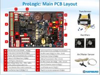
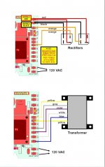
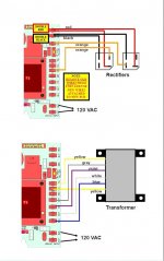
Based on the pictures below. Two Orange Wires (J) with 24 VAC are going to the rectifiers, one to each rectifier. Red and black are coming back from the rectifiers with 18-33 VDC and red and black are connected to each other.

Can anyone explain how this circuit works. I understand that rectifiers use diodes to convert AC to DC, but then why use two rectifiers and why are red and black connected to each other and also why do the two orange go to separate rectifiers (assuming one orange wire is hot and one orange wire is neutral with 24 VAC)?


ProLogic Main PCB Layout.jpg
Rectifier and Transformer Wiring Instructions.jpg
 

Enjoying this content?

Support TFP with a donation.

Give Support
Thread Status
Hello , This thread has been inactive for over 60 days. New postings here are unlikely to be seen or responded to by other members. For better visibility, consider Starting A New Thread.