
Automation of INTEX SWG
- Thread starter tonyflores1006
- Start date
You are using an out of date browser. It may not display this or other websites correctly.
You should upgrade or use an alternative browser.
You should upgrade or use an alternative browser.
Updated schematic, with labels for clock and data lines swapped. Labels renamed to DIO / CLK to match Intex naming standard
Swapped +5V and GND on the Intex connectors.
It might be that the whole connector needs to be reversed? (Easily fixed by rotating the connector, if so)
Looks like the connector has a little dot on GND on the picture, signifying pin one?
@jressel01: Can you look at the rendered board layout below, and see if the connector looks the right way, for plugging the display connector into?
EDIT: See below for updated schematic
Rendered board:
(same size as original perfboard design, but the mounting holes are a bit further away from the edges)
EDIT: See below for updated board layout
Last edited:
Rotated the Intex connectors 180 degrees
Schematic:
EDIT: See below for updated schematic
Board render:
EDIT: See below for updated board layout
I'll upload the gerbers when I've verified everything
Schematic:
EDIT: See below for updated schematic
Board render:
EDIT: See below for updated board layout
I'll upload the gerbers when I've verified everything
Attachments


Last edited:
Ok, I've dismantled my Intex SWG, and connected everything together. Still no response from the main board, or lights in the display board. I've verified that everything is connected correctly.
I'm starting to wonder if my controller board uses a different LED controller than the one used on on the board that @tonyflores1006 has. He has a board with a electrolytic capacitor on front, mine is without that capacitor.
( I've got the same board as @jressel01 )
The TM1650 is a 16 pin chip according to the datasheet, on my board there is a unmarked 18 pin LED controller. I'll have to look into what kind of chip that is, and if it makes any difference at all for the ESP32 code
Dismantled my Intex sandfilter pump, which _does_ have a TM1650 on the display board. Unfortunately it appears that the pins for 5V and GND are reversed on the pump, which explains why I had the connections reversed in my first schematic design. Need to update the schematic/pcb with some jumpers.
@tonyflores1006 are you able/willing to share the code for the sandfilter pump aswell?
@tonyflores1006 are you able/willing to share the code for the sandfilter pump aswell?

Thanks, it fits with my pinout measurements aswell. I looked at several LED controller, and didn't find anything matching the pinout. So an PIC 16F88-I/SO looks plausible.@Jings i Think they use something like this PIC 16F88-I/SO MCU and write own Code for it.
Need to dig out my logic analyzer to look at the signals, I guess.
Last edited:
Chris12345678
New member
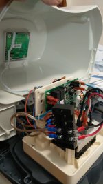
Hi,Bonus pictures of the project adapted and working for the Intex Krystal Clear pump. I could order the PCBs, but as I only need this one for myself and this way works, then is OK for me. The blue supports of the relay and main boards are made by me using with my 3D printer and we're designed using Fusion 360. In the last picture, a wifi antenna can be seen... This was necessary due to the distance with my router.
just came across this cool project. Awesome, thx, @tonyflores1006! Seems exactly what I was looking for to make my Intex Sand Filter Pump SF70220RC-2 an IoT device.
Unfortunately I have no experience in soldering a PCB like @tonyflores1006 did from scratch. Also didn't never use gerber files like @Jings is designing to order PCBs ever before.
But I know how to 3d print and I once programmed an ESP32 - based IOT device with Arduino-IDE and added it to my smart home.
Is anyone currently making this project for a SFP like SF70220RC-2? @Jings? @jressel01? @stealthrt? @OneAn9ryN00b?
At this occasion, how about making 2 sets, one for you and selling one to me?
Due to bad Wifi coverage, mine should also have that external antenna like seen in @tonyflores1006 picture
")
Where could I find the 3d files for printing the supports?
Thx
Chris
Last edited:
@Jings
i must replace my SWG. Warrenty by Intex and get an old one with the same board from tonyflores1006. The code work without any problems. You find a way for the new Board?
I try with my logic analyzer and dont find it for now.
because i have 2 SWG one old and one new
i must replace my SWG. Warrenty by Intex and get an old one with the same board from tonyflores1006. The code work without any problems. You find a way for the new Board?
I try with my logic analyzer and dont find it for now.
because i have 2 SWG one old and one new
I have a different board from the one that is shown in the previous posts. Seems to be the same pinout for the 4-pin connector and 16 pin TM1650 but I haven’t confirmed that yet.

@stealthrt you can use the code but you must change the button code and add some http post for the buttons.
By button code do you mean this?
Not able to find the http post calls you mentioned for me to change?
Code:
#define clockPin        GPIO_NUM_19
#define dataPin         GPIO_NUM_18
#define clockDispPin    GPIO_NUM_17
#define dataDispPin GPIO_NUM_16You must define HTTP_Posts for your buttons and must add Code that they work.(RestServer.ccp and so on)
In the code ist only something for Power and Selfclean
You must look on with Pins the button connect an in the Dokumentation Folder you find Doku for the IC.
It was not easy
In the code ist only something for Power and Selfclean
You must look on with Pins the button connect an in the Dokumentation Folder you find Doku for the IC.
It was not easy
So I'm looking at my version of the ESP32 that I have (Known as the Lolin32)

And looking at the schematic I see they call out GPIO 16, 17, 18 & 19. However, I do not have the same pin layout as they do...Go figure...
- GPIO 19 -> SWG main board clock
- GPIO 18 -> SWG main board data
- GPIO 17 -> Display board clock
- GPIO 16 -> Display board data


So, I take it my layout would be:
That look correct?
And looking at the schematic I see they call out GPIO 16, 17, 18 & 19. However, I do not have the same pin layout as they do...Go figure...
- GPIO 19 -> SWG main board clock
- GPIO 18 -> SWG main board data
- GPIO 17 -> Display board clock
- GPIO 16 -> Display board data
So, I take it my layout would be:
| ESP32 DevKitC | ESP32 Lolin32 | |
| GPIO 19 | -> | GPIO 19 (MISO) |
| GPIO 18 | -> | GPIO 18 (SCK/CLK) |
| GPIO 17 | -> | GPIO 17 (TX) |
| GPIO 16 | -> | GPIO 16 (RX) |
That look correct?
Last edited:
@tonyflores1006 thx it works. Integration to Homeassistant
Now i order PCB's and make it nice.
Now i order PCB's and make it nice.
Attachments


@jressel01
I've got some gerbers laying around. Unfortunately, as I have the non TM1650 version, I've got several revisions of the layout. Need to sort out which is which.
I've got a "jumper version" somewhere that allows swapping of the +5V and GND lines on the connectors, if we someday get some working software for the non TM1650 version
On the TM1650 version, the +5V line is to the "right outside" correct?
yes +5v and Gnd switched@jressel01
I've got some gerbers laying around. Unfortunately, as I have the non TM1650 version, I've got several revisions of the layout. Need to sort out which is which.
I've got a "jumper version" somewhere that allows swapping of the +5V and GND lines on the connectors, if we someday get some working software for the non TM1650 version
On the TM1650 version, the +5V line is to the "right outside" correct?
yesSo, I take it my layout would be:
ESP32 DevKitC ESP32 Lolin32 GPIO 19 -> GPIO 19 (MISO) GPIO 18 -> GPIO 18 (SCK/CLK) GPIO 17 -> GPIO 17 (TX) GPIO 16 -> GPIO 16 (RX)
That look correct?
I finally manged to get some time to cleanup all the different revisons of the PCBs.
This is the pcb/gerbers for the Displayboard version with a TM1650 chip

 github.com


This is the version with jumpers that allow swapping of the GND/+5V lines on the connectors:
 github.com


(If anyone spots any mistakes, please send me a message)
This is the pcb/gerbers for the Displayboard version with a TM1650 chip
GitHub - jingsno/intex-swg-pcb-TM1650: Intex SWG w/TM1650 display board
Intex SWG w/TM1650 display board. Contribute to jingsno/intex-swg-pcb-TM1650 development by creating an account on GitHub.
github.com
This is the version with jumpers that allow swapping of the GND/+5V lines on the connectors:
GitHub - jingsno/intex-swg-pcb: Intex SWG with jumpers
Intex SWG with jumpers. Contribute to jingsno/intex-swg-pcb development by creating an account on GitHub.
github.com
(If anyone spots any mistakes, please send me a message)
Thread Status
Hello , This thread has been inactive for over 60 days. New postings here are unlikely to be seen or responded to by other members. For better visibility, consider Starting A New Thread.