Aquatrol SWG no power

Confirmed power at box and inside unit. So doing my research I downloaded the fabulous Aquatrol diagnostics guide. Thank you internet for whoever created that guide!

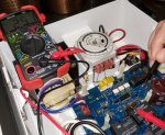
Following through the steps I found that I did not have the correct 18-33 VDC between black and red wires so I replaced the rectifiers with part GLX-DRK. I now have 31 VDC between black and red on the main board.

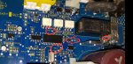
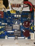
Continuing to follow the guide, checked step H for PCB, reseated no apparent issues there. I do not have any voltage on pins 1 and 3 coming off the main board. It continues to say visually inspect for any damage but the board is in pristine condition. Am I just looking at replacing the PCB? Any other tips or things I should check? Including a Pic of the main board.
 

Attachments

  • 15979466092162772829137830373334.jpg
    15979466092162772829137830373334.jpg
    601 KB · Views: 24
What seems to be the problem? Your sig says T-15 cell, please confirm?
First off, the Aquatrol model is designed for 120VAC operation. The incoming AC jumper setting is not applicable. Aquatrol Owners Manual

The output voltage from the Bridge rects should measure 22.6Vdc unloaded. When the Black and Red wires are connected to the board the caps get charged. Hence, the 30-33Vdc.
If you are having an issue as in "No Display, No Lights" probe TP13, TP14 and Pin#4 for 5Vdc as shown in the below pic. Perform the voltage test without the Display bd in place.
Follow the instructions here: AquaTrol has no lights nor display

Fyi, the Aquatrol and Aquarite share the same onboard Low voltage power supply
Hayward Aquarite SWG - Further Reading

15979466092162772829137830373334_1.jpg
 
What seems to be the problem? Your sig says T-15 cell, please confirm?
First off, the Aquatrol model is designed for 120VAC operation. The incoming AC jumper setting is not applicable. Aquatrol Owners Manual

The output voltage from the Bridge rects should measure 22.6Vdc unloaded. When the Black and Red wires are connected to the board the caps get charged. Hence, the 30-33Vdc.
If you are having an issue as in "No Display, No Lights" probe TP13, TP14 and Pin#4 for 5Vdc as shown in the below pic. Perform the voltage test without the Display bd in place.
Follow the instructions here: AquaTrol has no lights nor display

Fyi, the Aquatrol and Aquarite share the same onboard Low voltage power supply
Hayward Aquarite SWG - Further Reading

View attachment 159048
Yes that's right a T15. I had noticed the pump wasn't running, went out to check and had no power to pump or the unit as no leds and no display.

I mentioned above I had run through the diagnostic guide, but got hung up checking those riser pins to the DSP board. However, I didn't trust my voltmeter because it had an unfortunate runin with some voltage a while back, so I picked up a new one. I rechecked pins 1 & 3 on those riser pins and have good voltage there. According to the guide, I should look at replacing the DSP, but I'll look over what you have provided. Thanks!
 
The AquaTrol takes a T-5 cell.

How are you measuring the salinity and does it match the box reading?

You might be able to convert to T-15 by connecting the two solder points at J4, but I'm not sure that that will work with the Aquatrol.

Note: The J4 jumper is below the J7 jumper. The J7 is labeled Primary/secondary.
 
Yes that's right a T15. I had noticed the pump wasn't running, went out to check and had no power to pump or the unit as no leds and no display.

I mentioned above I had run through the diagnostic guide, but got hung up checking those riser pins to the DSP board. However, I didn't trust my voltmeter because it had an unfortunate runin with some voltage a while back, so I picked up a new one. I rechecked pins 1 & 3 on those riser pins and have good voltage there. According to the guide, I should look at replacing the DSP, but I'll look over what you have provided. Thanks!
Pin 4 on the header (left to right) carries the incoming 5Vdc supply to the Disp bd. Remove the disp bd and confirm 5 Vdc is present at pin4. If ok, connect the disp bd and place the switch to Auto. Measure the dc voltage from pins 1-7 with respect to the Negative post R15 on the mainboard and report back.
 
The AquaTrol takes a T-5 cell.

How are you measuring the salinity and does it match the box reading?

You might be able to convert to T-15 by connecting the two solder points at J4, but I'm not sure that that will work with the Aquatrol.

Note: The J4 jumper is below the J7 jumper. The J7 is labeled Primary/secondary.
I know right? Noticed the OP has a newer pcb and interestingly, it has a K4 relay. I am guessing the cell type is available in the setting.
@OP, mind sharing the pcb sw rev?
 
I am guessing the cell type is available in the setting.
I don't think that the AquaTrol is designed to take anything but a T-5.

It might take a T-15 if you jumper the J4 jumper, but I don't know that for sure.

I suspect that the cell is a T-5 or the salt is a lot lower than they think.

How old is the system?

Has the cell ever been replaced?

Do you have a reliable test for salt like a K-1766 salt test kit or a calibrated salt meter?
 

Enjoying this content?

Support TFP with a donation.

Give Support
Thanks for the responses all. Sorry all I misspoke, it is a T5, that's what I get for trying to remember when not at home!

The board is labeled as Hayward Industries 2013, G1-0660120-1, REV A

Updated TESTS all with negative lead on R15 post.
This is plugged in with DSP removed

TP13 5V
TP14 0V
PIN 4 25V


With Reseated DSP
PIN 1 0V
PIN 7 59V
 
I would assume the 25V at Pin 4 is a user error. Are you sure the Multimeter is properly set to measure DC voltage?
If 5Vdc is present at TP13 but TP14 reads 0 that means, U13 went bad. There can never be 25Vdc at Pin 4 if TP14 reads 0 volt. The max operating voltage of the onboard chips is 5.5Vdc.

Please reference the GLX-PCB-RITE R1.59 Circuit Diagram
If you can interpret the schematic diagram, it shows that the current is flowing from left to right.
TP-3 represent TP13 on the bd, TP-4 is TP-14 and TP-5 is tied directly to PIN4 (header)
 
Yes TP-3 and TP-4 on the schem is the same as TP13 and TP14 on the bd. Correct, you need 5 Volts dc not mV.
Unplug the AC power to the bd, set the multimeter to measure Ohms (Ω). Measure TP14 and PIN4 resistance against R15. It should be in K or M range and nowhere closer to zero ohm.
If you are keen to test and able to solder, remove the U13 chip from the pcb. Temporarily solder a switching diode or any 1A diode across TP13 and TP14. Make the sure the Cathode side is facing towards TP14. Plug in the DSP and see if it power up. This is a risky business and you should not let it run for long. Otherwise, just replace the U13 chip.
 
So I have 9 M ohms between R15 and TP 14
I have 22 K ohms between R15 and pin 4

Thanks for your detailed responses. I definitely am not a certified electrician, but did manage to replace some capacitors on an old Xbox. While the solders were not pretty to look at, it did work :)

If I'm reading diagram, I have a problem before TP 1 since I'm reading mV there and not the expected 24V, right? Wouldn't it be that I have an issue at U7?

U13 comes into play after that yes?
 
Resistance is good.
You stated in your previous post that 5Vdc is present on TP13. Please confirm! For this test, all Voltage should read V and not mV.
 
Understand your confusion. This could be my misunderstanding of what TP1 and TP2 represents on the above linked diagram. I'm attaching a Pic of what I'm probing circled. I'm using TP 1 just below U3, TP 2 above U3, TP 14 to the right and TP 13 further off to the right. There is also a TP 3 below U3 but I am understanding this is NOT the same TP 3 as in the above linked diagram.

According to that diagram it says I should have 24V on TP 1, which I don't, unless I'm not clear on what TP 1 should be in the diagram.

My measurements are - -

TP 1 75 mV
TP 2 75 mV
TP 13 5V
TP 14 0

TP 3 81 mV
 

Enjoying this content?

Support TFP with a donation.

Give Support
Thread Status
Hello , This thread has been inactive for over 60 days. New postings here are unlikely to be seen or responded to by other members. For better visibility, consider Starting A New Thread.