C0d3Sp4c3
Well-known member
- Dec 10, 2018
- 333
- Pool Size
- 20000
- Surface
- Plaster
- Chlorine
- Salt Water Generator
- SWG Type
- Hayward Aqua Rite (T-15)
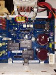
NO, the TP's on the schematic diagram does not match the actual TP's on the mainboard. The TP-1 on the schematic diagram is referring to the output voltage of the 24V regulator which is pin 3 of U7.
Please ignore the schematic for now to avoid confusion.
If 5 Volts DC (not mV) is present on TP13 on the mainboard but TP14 is 0, then the U13 chip failed. If U13 is good, expect 5 Volts DC on TP14 as well.
Please confirm you have 5Vdc on TP13, that's all I need to know for now.
Please ignore the schematic for now to avoid confusion.
If 5 Volts DC (not mV) is present on TP13 on the mainboard but TP14 is 0, then the U13 chip failed. If U13 is good, expect 5 Volts DC on TP14 as well.
Please confirm you have 5Vdc on TP13, that's all I need to know for now.


