Again, the biggest mystery is why if SUPERFLO pump is set to EXTERNAL MODE does the pump show 0 speed (which maybe is what is causing the pump to not go on even after getting signal from automation).

Aquarite P4 connection to Superflo (as a two speed pump) - PUMP DOESN'T TURN ON BY AUTOMATION
- Thread starter BruceMAbrahams
- Start date
-
- Tags
- pool automation
You are using an out of date browser. It may not display this or other websites correctly.
You should upgrade or use an alternative browser.
You should upgrade or use an alternative browser.
I would open the splice and try the connections directly.
The cable that connects to the pump has 6 wires, red, green, yellow, orange, brown and black.
The red wire should test as 5 volts against the black wire. Check that.
If that checks out, connecting the red wire to the green wire should turn on speed 1.
Red to yellow should turn on speed 2.
Red to orange should turn on speed 3.
Red to brown should turn on speed "quick clean".
Don't connect red to black.

I will do it tomorrow. Unfortunately, I don't own the voltmeter and don't know when I can get my friend to come again...but I can try. Also, to answer your question, NO speed lights turn on when automation thinks pump should run. But the light goes on for SPEED at the right with a zero in the display.
You can get a multimeter at any hardware store. YouTube has plenty of videos on how to use them.
Just turn off power and open the splice.
Separate the wires and do the tests. It's low voltage, so there's not a big risk.
Only do what you feel comfortable doing.
Just turn off power and open the splice.
Separate the wires and do the tests. It's low voltage, so there's not a big risk.
Only do what you feel comfortable doing.
First thing this morning, I undid splice and thought I would send you the picture.
The 8 wire cable from the pump has the following wires that are cut/unused: Purple, brown, grey, green
The black and white splice into the BLACK which goes to the automation / filter pump line in.
The red goes into the WHITE which goes to the automation / filter pump line in.
The blue goes into the GREEN which goes to the automation / aux 2 line in.
Obviously, the cut/unused have never been needed (since they are not connected to anything and pump was working both high and low speed from automation/aux 2 and from keypad pressing filter button).
Therefore, there is nothing to test here. Somehow the ridiculousness of this wiring functioned perfectly with this pump for 2 years. This is why I keep coming back to some setting on automation or pump. <and the person who did this is on vacation so I can't even get him or ask him anything>
The cable going into the pump is not the correct cable.
Go through the pump manual and make sure that you're doing everything correctly.
If that checks out, then I would replace the cable with the correct original cable and rewire it correctly with no splice.
When you get the new cable, test to see if the pump turns on by connecting the wires as previously described.
Check the continuity of the right two screws of the filter relay with the filter pump relay on and off.
Bruce,
If you had the 5 VDC on the output of the relays, that means your relays are working... Logically, the problem has to be the cable or the pump or pump set up.
Thanks,
Jim R.
If you had the 5 VDC on the output of the relays, that means your relays are working... Logically, the problem has to be the cable or the pump or pump set up.
Thanks,
Jim R.
It has to be pump setup. I believe superflo pump doesn't work well with hayward aquarite p4 which is why he did the wiring he did (which worked without needing to speed $200+ on pentair intellcom 2 link to hayward) but the loss of the pump configuration was big. I need a voltmeter or multimeter, do you have a recommendation based on what you know I need to do (and simplier the better because I am not a handy person)?
The black and white wires are connected to the black wire. So, the black or white has to be the 5 volt.
Blue and red have to be speed 1 and speed 2.
Open the splices and connect the white or black to the red or blue.
The hardware store should have a simple multimeter for about $10.
Blue and red have to be speed 1 and speed 2.
Open the splices and connect the white or black to the red or blue.
The hardware store should have a simple multimeter for about $10.
Home Depot (cheapest):
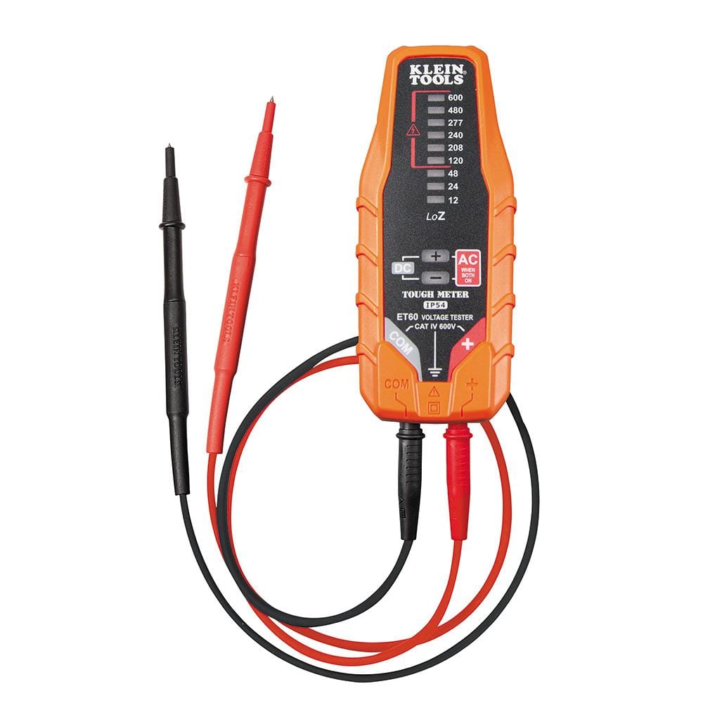
What do you think of this:
Klein Tools Electronic AC/DC Voltage Tester ET60 - The Home Depot
ET60 is a solid-state, low impedance, electronic voltage tester. It measures AC/DC voltages up to 600V. The ET60 does NOT require batteries; it is powered by the applied voltage. It is excellent choice
www.homedepot.com
What do you think of this:
Crenova MS8233D Auto-Ranging Digital Multimeter Home Measuring Tools with Backlight LCD Display - - Amazon.com
Crenova MS8233D Auto-Ranging Digital Multimeter Home Measuring Tools with Backlight LCD Display - - Amazon.com
www.amazon.com
Okay, we are on to something. When I removed splice and touched black and then white to RED, nothing happens!
The second multimeter should be good for what you need.
We need to verify if one of the wires has 5 volts.
Right now, it looks like a cable problem or a configuration problem.
We need to verify if one of the wires has 5 volts.
Right now, it looks like a cable problem or a configuration problem.
I ordered the multimeter. I am trying to understand how to measure a single wire with the two probes. In our case, we have a wire ending in a screw in the automation system. Where do I put the two (black / red) probes to measure volts? I know this sounds really basic...but I have never done it.
Take apart the wires at the splice. Put one test lead on the outside bond wire and the other lead on the individual wires to see which one is 5 volts.
This is the original wire.
 www.inyopools.com
This is the original wire.
Pentair Superflo/Super Max Pump Digital Comm. Cable Kit - INYOPools.com
Superflo/Super Max Pump Digital Comm. Cable Kit
www.inyopools.com
Ugh, I am so sorry that I don't know what "outside Bond Wire" means. Perhaps you can tell me the color or which pic you are talking about.
I assume you mean the other lead goes to each of the color wires RED, BLUE, BLACK and WHITE as per prev pic. one at a time for measurement.
I assume you mean the other lead goes to each of the color wires RED, BLUE, BLACK and WHITE as per prev pic. one at a time for measurement.
One lead goes on any ground wire and the other is connected to each colored wire individually until you locate the wire with 5 volts.
Thank you for your responses and patience, you truly are fantastic.
Since the splice is gone. We have the 4 wires coming from the pump (red blue black white) and we have three wires coming from the automation (black white green).
I know you want me to measure the volts coming from the wires from the pump. So one lead goes on red (let's say) and the other lead goes??? (What color is the ground wire)
Thread Status
Hello , This thread has been inactive for over 60 days. New postings here are unlikely to be seen or responded to by other members. For better visibility, consider Starting A New Thread.