Aquarite P4 connection to Superflo (as a two speed pump) - PUMP DOESN'T TURN ON BY AUTOMATION

BruceMAbrahams

0
Bronze Supporter
Jul 25, 2017
47
Plantation, FL
Until board burnt out, system worked as follows:
Automation would turn pump on based on TIMER1 9am-11am at high speed
Automation would kick in TIMER2 from 11am-5pm at low speed. Aux2 light would come on.
I could manually turn pump on by pressing filter button and pressing it again would bring about low speed.

Okay, before replacing board, I wrote down the configuration:
TIMERS:
T1-ALL was 9-11am
T2-ALL was 11-5pm
AUX2-ALL was 11-5pm

CONFIGURATION:
Filter Pump was 1 speed
Aux 1 was solar
Aux 2 was timeclock, relay was standard, interlock disabled, freeze disabled
Valve 3 was solar

However, I didn't remember to write down the display on superflo pump.
After replacing board, pump will not turn on (I can run pump on its own timer) by automation. I have tried EXTERNAL MODE on and off, set speeds 1,2,3 and quick and even reset to default settings.

I confirmed that something is wrong after the new board was installed by reinstalling the old board (only burnt out place where reading salt chlorinator) to see if pump will go on as prior and it does not. This tells me that the issue is some setting - perhaps on the pump or something in the settings I am missing. Since no wiring change was done and it can't be the wiring.

Thoughts?

Thanks.
 
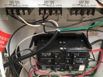
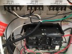
On the filter pump relay there are 4 silver screws. The first two have wires. The next two have no wires. Check for continuity between the right two screws when the filter pump is supposed to be on.

Don't check the right two screws.

For the right two screws, check the voltage from each to ground. It should be a 5 volt signal voltage. I think that it's dc, but check on ac and dc.

Note: Don't do anything that you're not comfortable doing. If you're not sure about testing voltage, don't do anything
 
Thanks. Before I hire an electrician to test this at $120 (because I don't know this stuff), is what you suspect consistent with the fact that when the automation tells the pump to go on, the display on the pump says 0 under SPEED. I was (probably incorrectly) assuming that this means the automation is telling the pump to go on and the pump knows to go on but is not going on because it can't if the speed is zero (and yet, each button on the pump display if pressed shows a speed)?
 
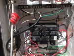
There's a control wire coming out of the side of the pump. The wire in the box looks like a different wire. The wire in the box looks like a piece of light wire?

Are the wires spliced?
 

Enjoying this content?

Support TFP with a donation.

Give Support
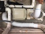
Okay, getting organized...there are three things coming off of the pump:
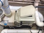
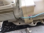
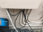
A black cord - picture 1
A green cord - picture 2 (goes into ground so I assume this is the grounding wire)
A grey conduit - picture 3 (holds everything heading towards automation box)
Sorry but I don't know what control wire means, etc., nor what "box" you are talking about.

The interesting thing is that we changed nothing with the wiring when we replaced the board.
 
The black cord is the control cable. It has 6 wires that are supposed to connect to the relays. The wire connected to the relays is a scrap piece of light cord.

So, something is not making sense. Where does the black cable go to?
 
Bruce,

The cable between the pump and the automation is not the right one, but if it has been working that is not the issue..

The manual says this... Note: If the pump has been stopped via the Start/Stop button, the pump will not run until the pump is turned back on by pressing the Start/Stop button. If the Start/Stop LED is illuminated, that indicates the pump is on and will run via Digital Inputs.Note: If multiple low voltage triggers are present it will be resolved by this priority: Quick Clean, Speed 3, Speed 2, and then Speed 1.


If you have a voltmeter, I think that the two black wires on the Pump/Filter relay should have a constant 5 VDC.. The white wire should have 5 VDC when the pump filter relay is energized. The green wire on Aux 2 should have 5 VDC when the Aux 2 relay is energized..

Thanks,

Jim R.
 
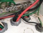
The cable connected to the pump is not the same as the cable going into the automation box. So, the wires must have been spliced together. I'm thinking that the splice might have been disturbed during all of the activity.
 
The correct cable is 25 feet long... How far away could the automation be??

I think that whoever wired it made a DIY plug to connect to the SuperFlo... but I'm just guessing...

It makes sense to follow the cable from the automation back to the pump and see if it goes all the way or if there is a splice.

Jim R.
 
Bruce,

You want the power to the pump shut off when you open the splice.. You do not want to short the 5 VDC coming out of the pump (on the Red wire) to ground.. Once you let the smoke out, you will not be able to get it back in...

Jim R.
 
I remember the splice was needed because the cord wasn't long enough (probably didn't use proper cable but it worked).
Everything you wanted us to test came up 5 VDC as per your instructions.
I did not remove the splice (see pic) since it wasn't touched or moved.

The black cable goes to splice and comes into box (green white black):

The black IMG_2531.JPGIMG_2532.JPG
 

Enjoying this content?

Support TFP with a donation.

Give Support
Thread Status
Hello , This thread has been inactive for over 60 days. New postings here are unlikely to be seen or responded to by other members. For better visibility, consider Starting A New Thread.