Air bubbles in two spa returns

So if it defaulted back to CLEANER as the 3rd speed, the dipswitch may already be moved to ON.
Do you understanding how the wiring works on the relays? Can you tell if the booster pump wiring is set up to the Lower left relay which is called AUX 1? You would follow the conduit from the booster pump to the cabinet, then follow the wires if they go to AUX 1 relay.
Most booster pumps are 240V, so there will be 3 wires - 2 hot wires to the relay and 1 ground to the ground bar.
You could turn off the circuit breaker to the booster pump first. Each pump should be on its own CB.
You can take photos and post back for guidance.
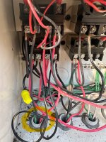
Ok this is a heck of a mess of wires but here in the photos is my best attempt at displaying for you.
FYI all my dip switches seem to be in the off position. Photo of that as well as a photo of the buttons on the main board and how they are labeled.

Photo with the faint red circles showing where the two wires from the conduit are hooked up. Photo of the conduit with the yellow circle just showing that is the conduit for the booster pump.
To me it looks as though the booster pump is wired to the Filter Pump Aux and other things are wired to Aux 1. But that is just me looking at these photos and wiring.
Added a photo of the Aux labels from my iAquaLink as well which clearly shows Aux 1 as pool light, Aux 2 as cleaner and Aux 3 as spa light. To me it seems like whoever installed all of this stuff prior to me owning the house clearly did not know what they were doing. FYI there are light switches mounted on the side of my house that can control the lights as well so that conduit is underground but I am sure I could figure it out.
IMG_3243.jpeg
 

Attachments

  • IMG_3244.jpeg
    IMG_3244.jpeg
    441.5 KB · Views: 9
  • IMG_3242.jpeg
    IMG_3242.jpeg
    302.7 KB · Views: 7
  • IMG_3241.jpeg
    IMG_3241.jpeg
    316.8 KB · Views: 9
  • IMG_3245.png
    IMG_3245.png
    108.2 KB · Views: 4
Last edited:
Photo with the faint red circles showing where the two wires from the conduit are hooked up. Photo of the conduit with the yellow circle just showing that is the conduit for the booster pump.
To me it looks as though the booster pump is wired to the Filter Pump Aux and other things are wired to Aux 1.
I have been looking at these photos and tend to agree. However, this would mean the booster pump turns on every time the filter pump turns on and I do not think that is happening. Are you positive the Yellow conduit is the Booster pump?

The way the relay works is that there are 4 terminals - Jandy labels them 2, 4, 6 & 8 for some reason. I just refer to them as 1 -4 from left to right. Terminals 1 and 3 receive power from circuit breaker and terminals 2 & 4 only receives power when the relay is activated.

Where is the main VST pump connected? It is best to have the VS pump connected to constant power.
Maybe backup and take a photo of the full cabinet with all the relays.

See the attached which I did for my panel to confirm how each component is connected. My lights are 120V which is why they are routed through the GFCI receptacle. Also, I have not updated this drawing but my SWCG is connected to the LOAD side of the Filter Pump relay.

Also agree that the dip switches are not pushed to ON.
IMG_3230.jpeg
 
I have been looking at these photos and tend to agree. However, this would mean the booster pump turns on every time the filter pump turns on and I do not think that is happening. Are you positive the Yellow conduit is the Booster pump?

The way the relay works is that there are 4 terminals - Jandy labels them 2, 4, 6 & 8 for some reason. I just refer to them as 1 -4 from left to right. Terminals 1 and 3 receive power from circuit breaker and terminals 2 & 4 only receives power when the relay is activated.

Where is the main VST pump connected? It is best to have the VS pump connected to constant power.
Maybe backup and take a photo of the full cabinet with all the relays.

See the attached which I did for my panel to confirm how each component is connected. My lights are 120V which is why they are routed through the GFCI receptacle. Also, I have not updated this drawing but my SWCG is connected to the LOAD side of the Filter Pump relay.

Also agree that the dip switches are not pushed to ON.
View attachment 604012
I can tell you that the booster pump does not turn on every time the filter pump is on. I am pretty sure about the yellow conduit but will check again. My son in law use to be an electrician so maybe I can get him to come out and help me try to diagram out all the wiring better.
My only concern at this point really since I have all the automation working and it has been for several days, is what if the filter pump does not come on for some reason and my booster pump still does that would not be good. I believe I can currently turn on the booster pump without the filter pump running but I will test that today when I get home.
I am thinking if it does then it should be as simple as moving the wires for the booster to the correct Aux and turning the dip switch to on so the booster only comes on when the filter pump is running. Right? I can wire both the pool and spa light to the same Aux and have them come on at the same time to later hopefully setup spillover mode but that is a whole other topic for another time....LOL
 
My only concern at this point really since I have all the automation working and it has been for several days
That is why I am hesitant to suggest changes but more about asking questions how it is set up and any conflicts.
what if the filter pump does not come on for some reason and my booster pump still does that would not be good. I believe I can currently turn on the booster pump without the filter pump running but I will test that today when I get home.
The booster pump is just a centrifugal pump and is NOT self priming, which is why the suction plumbing of it is connected to the pool return. So if the filter pump is on then water is being pushed to the booster pump.

then it should be as simple as moving the wires for the booster to the correct Aux and turning the dip switch to on so the booster only comes on when the filter pump is running. Right?
correct. You really do not need to undo wiring. The starting diagram that should be on the inside of your cabinet - it is also shown in Post #56, shows where each of the relays plug into the PCB, These sockets go from left to right - FP, Aux 1, Aux2, etc.
All you need to do is switch which plug is put in which socket. Just document it because that does not follow the baseline diagram, but it saves moving a bunch of wires around once you know which device is connected to which Aux.
Based on the AUX labels
AUX 1 is Pool Light
AUX 2 is Booster Pump
AUX 3 is SPA Light
So just swap the plug for AUX 1 and AUX 2 and see if the Pool light comes when pressing AUX 2 on the panel or on the app.
I can wire both the pool and spa light to the same Aux and have them come on at the same time
If you elect to move the wires of each device instead of the just the plug for each relay, The pool light on Aux 1 can just move to the empty Aux 2 where the booster pump is set up. Just ensure it is done correctly as your booster pump is 240V and light appears to be 120V but your son-in-law can confirm that.

later hopefully setup spillover mode but that is a whole other topic for another time....LOL
Lets fix the other things first but it is doable.
This requires flipping another Dipswitch #3 and you will have to move the plug in on AUX 3 to another socket such as AUX 4 or AUX 5. Since Aux 3 is the spa light, you can try that now by just moving the plug in the AUX 3 socket to either AUX 4 or 5, then press that on the panel (if in service mode) or on the app (if in auto mode). If the spa light comes on then you know that aux socket works and now becomes the spa light and rename it in the LABEL aux section.

Note - anytime you are moving sockets or wires, it is best to shut down all power to the system, make the changes and then power back up.
 
  • Like
Reactions: hensler74
Thread Status
Hello , This thread has been inactive for over 60 days. New postings here are unlikely to be seen or responded to by other members. For better visibility, consider Starting A New Thread.