Allen,
I see no reason to have the AC power for the heater to be controlled by the IntelliCenter.
Thanks,
Jim
I see no reason to have the AC power for the heater to be controlled by the IntelliCenter.
Thanks,
Jim

A couple of things that I imagine you know but may forget at 0 dark thirty after its taken longer than expected to "adjust" the conduitSo thinking out loud here and comments welcome..
Posting the new and old panel in this thread gave me an opportunity to study the small differences between them. You would think swapping panels would be simple but a few differences make more work.
First, is that the knockoffs and their sizes are in different locations. The existing conduits are not going to line up with the IntelliCenter knockoffs and their different sizes. Just going to need to figure out how to align things when the old panel is off.
Second, The ground bar on the Aqualink is mounted at the bottom of the cabinet while on the IntelliCenter it is mounted in the middle. It does not look like most of the nine ground wires will not reach up to the IntelliCenter ground bar. I doubt there is much slack to pull wire up.
I think I am going to buy a separate ground bar and mount it in the bottom of the IntelliCenter.
Third, I have been questioning the best grouping of devices on circuit breakers.
Aqualink panel has:
I wired the IC for:
- 240V - filter pump, SWG, cleaner, pump, heater
- 240V - spa jet pump, spa blower
- 120V - Lights
- 120V - Aqualink
Which of the three 240V breakers should I put the heater on?
- 240V - filter pump (Intelliflo VSF) , Intellichlor SWG
- 240V - spa jet pump (2 HP Whisperflo)
- 240V - cleaner pump (PB4-60), Spa Blower
- 120V - lights
- 120V - Intellicenter
On the Aqualink panel if the filter pump CB trips it turns off the SWG, cleaner pump, and heater. All of which you don;t want running if the pump is off.
However if you notice my 20 year old panel is grandfathered and does not have GFCI CBs for the pumps or heater. The new panel will fix that.
I am more concerned that a GFCI trip caused by the cleaner pump or heater does not shutdown the pool. And the Intelliflo pump can be 11.8 amps while the PB4 pump is 6.4 amps which is pushing a 20 amp CB. Although the VSF pump is not pulling anywhere near 11.8 amps at the speeds I run it at even while cleaning.
I also think failure modes where the VSF pump fails and does not trip the CB are more likely then CB trip failures. That used to not be the case with SS pumps where most pump motor failures will trip the CB. With a VSF pump we see more drive failures where the pump doesn't run and the CB does not trip. Do I really accomplish much by loading up the filter pump CB with all four devices?
I would rather keep the other pumps and heater on separate CBs so if they trip the GFCI the pool continues to run and it is no big deal. I can fix things at my leisure.
The cleaner and the spa blower will never run at the same time. I will probably add the heater onto that CB.
Do I care that the MasterTemp heater has continuous power and is not switched by the filter pump relay load side? I don't think so. It is controlled by the firemans switch and has the water pressure switch as a backup. It would take multiple failures for the heater to run without the pump running and the IC demanding heat.
My risk in wiring it this way is if the filter pump CB trips while the cleaner is running the cleaner pump can run dry for up to 3 hours. And if it trips while the heater is running hopefully the water pressure switch in the heater will do its job and shut it down.
Although the MasterTemp Installation manual says:
Any switches in the pump circuit (including circuit breakers) that can disconnect the pump must also disconnect the heater.
Which has me rethinking on which CB to put it. Although the manual does not differentiate if the heater also has automation control from the firemans switch which gives a secondary safety.
Thank you for listening and if you think I missed anything let me know.
A couple of things that I imagine you know but may forget at 0 dark thirty after its taken longer than expected to "adjust" the conduit
1. Make sure that you wire the intelliflo to the line side of the filter pump relay
2. If you add the heater to the cleaner/spa blower circuit you'll either need to add it on the line side of the blower relay
Allen,
I see no reason to have the AC power for the heater to be controlled by the IntelliCenter.
Thanks,
Jim
Allen...Or on the same CB as the filter pump?


The blower continues to run, that’s why with newer heaters they should be on the line side, cool down periods should be enabled on all automations with heaters. Older heaters used to be on the load side for fear the heater would continue to run without flow. But newer heaters have so many fail safes SFS HLS THER FS, they would all have to fail.or does it shut the flame but keep the blower running for a short time for cool down?
When setting up the gas heater in the IntelliCenter it asks you for the minutes of cooldown delay you want.The blower continues to run, that’s why with newer heaters they should be on the line side, cool down periods should be enabled on all automations with heaters. Older heaters used to be on the load side for fear the heater would continue to run without flow. But newer heaters have so many fail safes SFS HLS THER FS, they would all have to fail.
That’s interesting. Given this configuration, it would seem the system supports control via the 24v control loop as well as line voltage power relay. Otherwise, I can’t figure what the delay setting would do. Can anyone confirm?When setting up the gas heater in the IntelliCenter it asks you for the minutes of cooldown delay you want.
…
How many times did you have to go to the hardware store for parts ? And how many electrical shocks did you get? If you say "none" and "zero" then we know you're lying ....


 www.wago.com
You deserve many beers … good jobBergen County NJ still has blue laws.Only essentials like food and drugs can be sold on a Sunday. If I needed any parts I would have needed to drive half an hour over the NY State line to the nearest open Home Depot.
Because of that I did a whole bunch of staring at the old versus new panels and thinking through what I may need. My helper in this project was only available on Sunday so I knew I needed to have all possible materials.
The right question is how much stuff and I returning to Home Depot this week that I did not use. Mostly gray electrical PVC stuff as I thought we would need to make more adjustments to the conduits then it needed.
View attachment 429044
Some observations on anyone replacing an Aqualink Load Center with a IntelliCenter...
The knockouts on the bottom of the cabinet are in different positions. Both the Aqualink cabinet and the IntelliCenter have one 1 1/4" knockout used for the main electrical feed in. However the Aqualink has this knockout centered on the bottom and the IntelliCenter has it towards the right side. This had other ripple effects on wire lengths described below.
I did not expect any of the electrical conduits coming up out of the ground to align with the IntelliCenter knockouts. We were prepared to be heating schedule 40 electrical conduit and bending it to get them aligned. I loaded up on 3/4" and 1 1/4" 45 degree sweeps and 90 degree sweeps and nipples to redo as much of the conduit as needed.
As it turned out with some creative positioning we got the electrical conduits into the cabinet. So all that stuff gets returned.
Another difference between the Aqualink cabinet and the IntelliCenter is that the IntelliCenter cabinet is taller so the relay connections are farther from the bottom electrical feeds. So not all wires reached the IntelliCenter relays.
And the ground bus bar on the Aqualink is at the bottom of the cabinet and is in the middle of the taller cabinet in the IntelliCenter. A few of the ground wires did not reach the IntelliCenter ground bus bar.
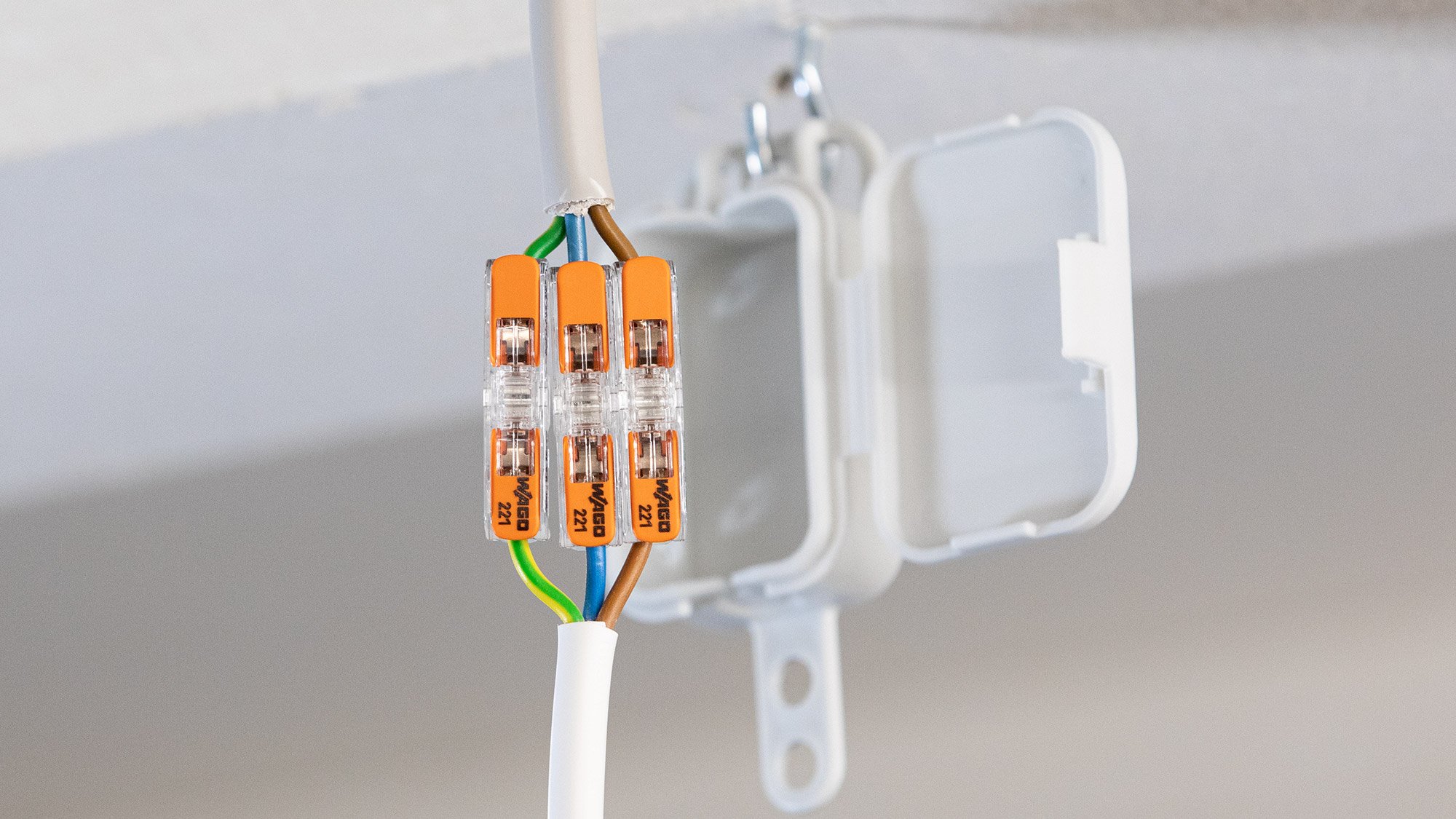
This would have really tripped me up if I had not seen the differences and planned for it. I had spools of wire to splice the wires and I used Wago 221 Inline Splices to neatly extend the wires.
null
A truly standard-setting solution for all conductor types from 0.2 to 4 mm², the new 221 Series Inline Splicing Connector with levers combines all the trusted advantages of the 221 Series Splicing Connectors into a slim design. Offering unsurpassed simplicity, speed and reliability, the 221...
It took me about 2 hours to disassemble the Aqualink panel and disconnect all the wiring and make sure each wire was labeled. Then we spent a good hour plus figuring out the panel mounting and routing of the electrical conduits. Then another hour plus wiring the high voltage side with all the splices needed to reach the relays.
As I said the IntelliCenter has the 1 1/4" knockout to the right and the bus bar connections for the main hots and neutral lines are all the way on the left. Those wires just barely reached. If they didn't I would have had a problem since I had a bunch of 12 AWG wire but did not have wire and splices for 6 AWG wire.
Then hooking up the low voltage side with the sensors and actuators and the RS485 devices.
My biggest fear was powering it up and getting a dead panel. I could see taking ita ll down and reinstalling the Aqualink to get the pool running. So it was a relief when the IntelliCenter screen lit up, all the CBs stayed live, and it was time to update the firmware. I needed to update the panel first to 1.47 and then to 1.64 by USB and that was uneventful.
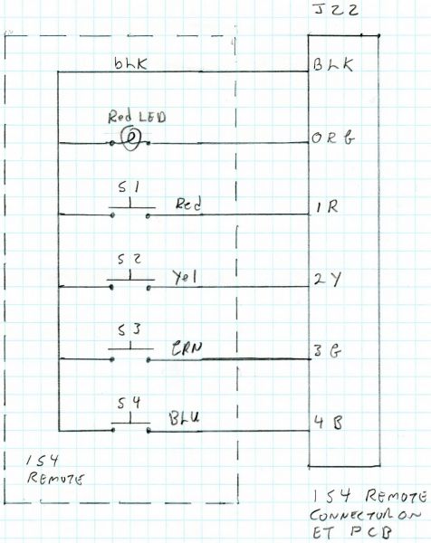
Then came all the setup which is not very intuitive from the outdoor control panel. After various tries I have the basics running with the pool, spa, and heater. I have a wireless bridge on order from Amazon to get the panel connected to my network. I need to get an IS4 SPA Controller for my spa. And I need to figure out various programming like how to tell it to increase the pump speed when running the heater in POOL mode.
And I got 0 electrical shocks. Main panel power was off before disassembly started and when panel was buttoned up and breakers on and it all worked. It helped that my helper who had wired ET panels before but not an IC was doing the wiring and I was looking over his shoulder doing QC. So I spotted the problems and got them fixed as we went along.
Overall it took a lot of planning and about 8 hours of work. I am happy I finally did it as now the automation has VS control over my VSF pump and can vary the speeds, and I have finer control over the % generation in the IntelliChlor, and the Intellichlor has separate % settings for POOL mode and SPA mode. Plus the color touch panels on the Outdoor Control Panel and The Indoor Control Panel are nicer then all the Jandy buttons.
Enough for today. I feel like I did an host days work.

 where the Pentair IS-4 Spa Remote is 6 1/2" wide. So in addition to the $300-$400 cost of the IS-4 it is not going to be a drop in replacement.
 www.troublefreepool.com
You might want to double check that before you connect it up.
On the EasyTouch you have to enable the IS4 before it will work, and you have to assign a circuit to each button number. I assume it is the same way in the IntelliCenter.

