Jon
Your IntellipH maximum allowed dispersal rate only allows only one-minute-of-dispersal-per-hour which is 1/60th of the previous calculation: 1/60 * 45gpd = .75 gallons/day = 96 oz/day. This assumes that the IntellipH can run all 24 hours if your pump is running for all 24 hours. That’s an assumption that is not clear in the manual. Can the IntellipH run for all 24 hours, or is it limited to the 8-hours/day that is illustrated (but not specified) in the manual?
Check.. So to answer your question, the answer is YES, but with other factors to consider. As you pointed out, the intellipH delivers/doses/dispenses acid every hour. The amount of acid "delivered" is determined by a percentage number, determined and manually set by the user at the ipH controller. 0% = 0 amount of acid dispensed (essentially no run time of the P. pump), all the way up to 100% = 60 seconds of acid dispensed every hour.

So, this occurs by use of an internal digital timer in the ipH controller. The controller begins a 60 minute countdown once the controller's power leads are energized. The power applied to the controller occurs at the same time that the filter pump circuit is energized within the automation.

So, this is the sequence of events...

1. Filter pump circuit is activated by the automation.
2. Power is now applied to the ipH controller. A 60 minute timer countdown begins.
3. After 60 minutes, the controller signals the peristaltic pump (P. pump) to begin pumping the 50% diluted muriatic acid solution.
4. The P. pump will continue to pump for as many seconds as determined by the ipH controller. (remember this pump time is actually determined and set by the user as a percentage number), up to a maximum of 60 seconds (100%).
5. The ipH then signals the P.pump to stop pumping the solution and begins the countdown once again.

This sequence of events occurs every hour, so long as the filter pump circuit is energized. Once the filter pump schedule is completed within the automation, the filter pump circuit is deactivated and power is then removed from the load-side of the relay that delivers power to the IC transformer. Now the ipH controller has no power, hence the cycle is complete.

So, the long answer given above to your question is: So long as the ipH controller has power, it will pump solution every hour. How much solution it pumps every hour is determined by the percentage value set by the user up to a maximum of 60 seconds (100%) per hour.

Some Stenners come with a built in timer (econT) but the user is still responsible for all run rate calculations. The econT comes with 24 timers that could be setup similarly (like the IntellipH) to run every hour/every day for a certain amount of time...however the minimum run time is one minute so that would require use of one of the lower flow stenners (ex ET210F dispenses .11oz/min) for use with MA dispersals. Unlike the IntellipH, there is no provision for dialing back those programmed dispersal times. The timers would have to be changed manually.
Essentially my timer is in the automation. It determines when the ipH controller is powered on or not.
I took a look at the Econ T Series... Right, the EconT is dummer that the IpH, because like you pointed out, a user cannot dial back the dispersal times (amount of seconds per hour of dispersal)..

Thanks Jon, maybe since your still around the corner, if you want to see if we can tackle this project together at some point, I'm all in. I still need to take a look at that buried tank solution you came up with. ;)
r.
 
Last edited:
If your pump is a 220 and the automation turns the power on and off then just do what i did....

Slave a second 220 receptacle off the pool pump power and plug a 220 Stenner in there. When the pump comes on, the Stenner comes on. Adjust dosing accordingly to the amount of time it's going to run.

 
Cliff, now I think you might be on to something here.. (y)
Here's how I'd do it on my controller. I'd cut off the power cord (or try to find a suitable connector for it), hook up +24V DC from a power source to my common port of one of my pi hat relays, and connect the 0V DC wire from the power source to the p. pump, I'd then connect the +24V DC end of the p. pump to the NO port on my pi hat relay.
Let me see if I got this. So in other words, ditch the ipH controller and then run 24v power directly from a pi relay to the pump. Hmm, but the Raspi is on my desk (currently anyway) and once I get the last of my parts and pieces, the Raspi will be connected to the 485 bus on the IntellliCenter. I think what you are pointing out would require the pi to be located at the pad. Initially, I had considered mounting it in the low voltage compartment of the IntelliCenter load center. That is still doable once things are ironed out I guess, but then I need to communicate with it via ip from my desktop.

I'd then setup a timer in my node-red software that runs every hour, flips the relay for 42 seconds, that would allow the +24V waiting at the relays common port to flow through to the NO side which completes the circuit. The p. pump would then start spinning which dispenses acid into the pool. After 42 seconds the node-red software would open the relay, breaking the connection and the p. pump would stop. This would be my initial test

Now it's time to fancy it up. I'd drag a dial to my node-red dashboard and do some maths to make the timer adjustable from the dashboard and add a button to the dashboard labeled 'Sour Squirt' which would just run the thing on demand for 30 seconds. I'd then fancy it up by interfacing it with the nodejs-poolcontroller software and add checks like is SWG running, check for SPA mode, etc. Safety stuff.

Like Jim said you can probably do the same thing directly with your Intellicenter. I'm not at all familiar with them but if you can set its programs to run in the seconds and feed it appropriate power to one of the relays you could go that route as well. I gave the Intellicenter manual a once over looks like there is 24V relays but they're AC.

I added a picture of what it'd look like in node-red and a screenshot of my iphone.
I like it....
 
The stock relays in the IntelliCenter have no NC contacts, just NO contacts.. The coil is powered by 24 VDC. In theory they are "High Voltage" relays and are normally used to control 120 or 240 VAC..
Jim R.
Jim,
Correct. The relays won't help.
But... @cmc0619, Cliff... Here is some additional information to throw out that might help this cause. This is what I do know...

1. I have two low voltage sources in the IntelliCenter. The Control system transformer. It provides low voltage AC power to the system (18Vac, 5A.) and to the IntelliValves (24Vac, 4 amps). So no good there.

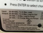
2. But then, there is the IntelliChlor transformer. It provides 24Vac (I think that's right),12A to the IntelliChlor Controller Circuit Board. The purpose of this board (amoIMG_5485.JPGng other things), is to convert that 24Vac power to 24Vdc, 7A which is usable power for the IntelliChlor cell and the IntellipH controller.


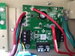
IntelliChlor Controller Circuit Board (located within low voltage compartment of IntelliCenter load center).


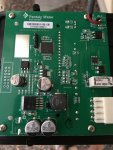
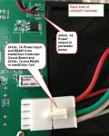
3. The IntellipH Controller reduces the amperage (I guess by the use of resistors) (I'm a bit "out of my lane" now) and uses 24Vdc 1A to send power to the peristaltic pump. So apparently the pump requires 24Vdc and draws about 1 amp.
IMG_5798.JPG IMG_5799.JPG 2020-05-08_19-54-04.jpg

So, bottom line is that I do have 24Vdc, 7 amps available from the IntelliChlor Controller Circuit Board, located in the IntelliCenter Load Center, that I can tap from, as this is the power utilized by the IntelliChlor cell and the IntellipH controller....

r.

Additional thought.... Not sure if this is helpful, but if there was need to install some additional small components (small relays, circuit boards, etc.) within the IntellipH controller housing, there is plenty of room.
 
Last edited:
Ron,

The SWCG board in your pic puts of about 40 VDC when the cell of not producing chlorine and about 35 VDC when it is producing chlorine...

I suspect the iPH board just uses a voltage regular to reduce it down to 24 VDC..

Jim R.
 
  • Like
Reactions: MyAZPool
Ron,

The SWCG board in your pic puts of about 40 VDC when the cell of not producing chlorine and about 35 VDC when it is producing chlorine...

I suspect the iPH board just uses a voltage regular to reduce it down to 24 VDC..

Jim R.
(y) Ah... okay Jim. Thanks, I certainly didn't know that. I just assumed that the voltage output to the cell must be the same as to ipH...
Thanks again sir...

Okay, so if that is the case, that would mean that the IntellipH controller gets that same power that is being deliver to the cell and would also receive 40Vdc/35Vdc.... How would that work????
 
Last edited:
Ron,

The SWCG board in your pic puts of about 40 VDC when the cell of not producing chlorine and about 35 VDC when it is producing chlorine...

I suspect the iPH board just uses a voltage regular to reduce it down to 24 VDC..

Jim R.
p.s. God help us if we could ever get some detailed specs/schematics of some of this equipment. :p Everything is so "proprietary" with Pentair!
 
How would that work????

Ron,

I assume the 40 VDC comes into the iPH and then goes to the SWCG unchanged. At the same time it goes to a regulator circuit in the iPH that reduces the voltage to 24 VDC which powers the iPH and acid pump motor. The only voltage the SWCG cell gets is the 40 VDC, so that is all you have to work with, as the iPH does not have any other source of power..

Just a guess on my part, but it kind of makes sense..

Thanks,

Jim R.
 
  • Like
Reactions: MyAZPool

Enjoying this content?

Support TFP with a donation.

Give Support
This is what i did.

Since you cant run lower than a minute you need to play either with how many times per week or you can further dilute your
acid, which helps a lot with corrosion and handling.

I have my schedule set one minute after start to make sure the pump is fully running and not in slow startup as it is a vsf, and
also to make sure the SWG is not running. My only doubt is this affects the initial readings of the SWG since acid is running while sensing.

I cant remember the voltage will test if you need info.

2D5BE80D-DDD7-4824-87ED-ECCEA6C1C13B.png
 
Last edited:
  • Like
Reactions: MyAZPool
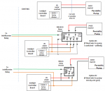
Here is what I was talking about eariler (I have been working on some relay stuff myself this week). Ron, if you truly have 24VDC power supply in the IntelliPH (not the one to the pump...that will be powered on/off for pump control), then this is pretty easy. AND if the black wire to your current peristalic pump is truly DC ground, then it is even easier. In both cases you need to add a relay into your intellipH and wire it appropriately, and then wire it up to one of the relays in your intellicenter.

The result is that you IntellipH controls everything as it does now, except when you want to manually inject using one of your Intellicenter relays to control. Seems to me it gives you the best of both worlds and doesn't introduce new parts into your system (yet).

1589001061591.png
 
  • Like
Reactions: MyAZPool
Ron,

I assume the 40 VDC comes into the iPH and then goes to the SWCG unchanged. At the same time it goes to a regulator circuit in the iPH that reduces the voltage to 24 VDC which powers the iPH and acid pump motor. The only voltage the SWCG cell gets is the 40 VDC, so that is all you have to work with, as the iPH does not have any other source of power..

Just a guess on my part, but it kind of makes sense..

Thanks,

Jim R.
Jim,
Okay, that makes total sense to me now...
You realize of course, that you just armed and launched an AIM-9 at my idea/assumption that I had consistent 24Vdc available to me in the Load Center. SPLASH ONE. :p
But also, you probably just saved me who knows how much $ in the cost of parts fried and countless donations to the household "cuss" jar. So thanks much!!

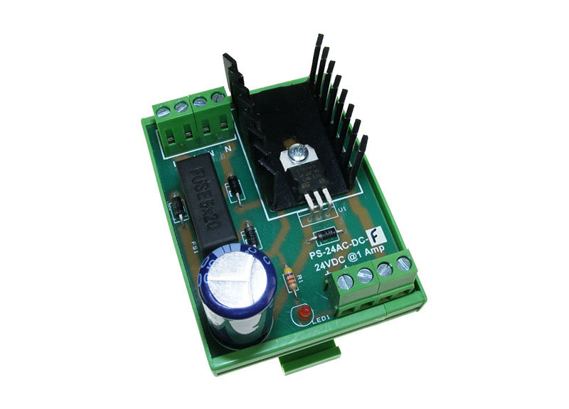
Moving on, I guess I could just try to rob some AC power from either the System Transformer (24Vac or 18Vac output leads) or the IntelliChlor Transformer (24Vac output lead) and use some sort of rectifier? or AC/DC converter, as an example, something like these. Thoughts? You know a lot more about electronics than I. Is this reasonable?

r.
 
Last edited:
  • Like
Reactions: Jimrahbe
Here is what I was talking about eariler (I have been working on some relay stuff myself this week). Ron, if you truly have 24VDC power supply in the IntelliPH (not the one to the pump...that will be powered on/off for pump control), then this is pretty easy. AND if the black wire to your current peristalic pump is truly DC ground, then it is even easier.

The result is that you IntellipH controls everything as it does now, except when you want to manually inject using one of your Intellicenter relays to control. Seems to me it gives you the best of both worlds and doesn't introduce new parts into your system (yet).

View attachment 137720
Jon,
Looks like my assumption was wrong. See post #30 and then my comments in post #33, above. Jim showed me the "errors of my ways". :p
Man, I like the schematics... Tell me what you think of my possible idea in post #33..
Thanks Jon!!!
r.
 
Jon,
Looks like my assumption was wrong. See post #30 and then my comments in post #33, above. Jim showed me the "errors of my ways". :p
Man, I like the schematics... Tell me what you think of my possible idea in post #33..
Thanks Jon!!!
r.
Sorry I missed that...In that case, you have to add that 24VDC power supply somewhere in the system and route it to the relay apprpriately. How about just get one that plugs into 120V somewhere and route it to the intelliph?

 
  • Like
Reactions: MyAZPool
idea/assumption that I had consistent 24Vdc available to me in the Load Center.
You could if you wanted too, just run the DC voltage from the SWG control board across another relay that would run with the pump so you would still have the safety of powering down the cell. Dont know it rectifiers have a lifespan.
I guess I could use rob some AC power from either the System Transformer (24Vac or 18Vac output leads)
This would scare me since its running the motherboard and you would push the transformer to its capacity. A DC power supply is cheaper than the risk.
 
  • Like
Reactions: MyAZPool
This is what i did.

Since you cant run lower than a minute you need to play either with how many times per week or you can further dilute your
acid, which helps a lot with corrosion and handling.

I have my schedule set one minute after start to make sure the pump is fully running and not in slow startup as it is a vsf, and
also to make sure the SWG is not running. My only doubt is this affects the initial readings of the SWG since acid is running while sensing.

I cant remember the voltage will test if you need info.

View attachment 137719
Felipe,
Very Interesting. So I perused that link you provided. You stole power from the output leads off of the IntelliChlor Controller Circuit Board?? 24Vdc? My understanding is the IC Controller board is supplying 35/40 Vdc to those leads because the cell requires it??
r.
 
Sorry I missed that...In that case, you have to add that 24VDC power supply somewhere in the system and route it to the relay apprpriately. How about just get one that plugs into 120V somewhere and route it to the intelliph?

Yep... Guess it doesn't really matter what voltage I am converting/stepping down from. So long as I end up with 24Vdc 1A right?
Nice!!!
r.
 
My understanding is the IC Controller board is supplying 35/40 Vdc to those leads because the cell requires it??
Im almost sure it was less than 30 since the cell is in diagnostic mode, i will check and get back to you.
DC motors dont care much about voltage, the higher the volts the higher the rpms(to a point of course).
Mine works, just make sure to check how much is your 60 sec worth in oz.
 
Last edited:
  • Like
Reactions: MyAZPool
Okay, So let's say I now have 24Vdc 1A in the Load Center. How I get it, i
Here is what I was talking about eariler (I have been working on some relay stuff myself this week). Ron, if you truly have 24VDC power supply in the IntelliPH (not the one to the pump...that will be powered on/off for pump control), then this is pretty easy. AND if the black wire to your current peristalic pump is truly DC ground, then it is even easier. In both cases you need to add a relay into your intellipH and wire it appropriately, and then wire it up to one of the relays in your intellicenter.

The result is that you IntellipH controls everything as it does now, except when you want to manually inject using one of your Intellicenter relays to control. Seems to me it gives you the best of both worlds and doesn't introduce new parts into your system (yet).

View attachment 137720
Jon,
Okay, lets say I now have consistent 24Vdc, 1A and I implement this, then yea, that would be how I could manually dose. Nice...
But how do I set/change the auto dose function remotely. What I mean is, how do I make a change to the "percentage" or how many seconds that it doses when the ipH is powered on without leaving the comfort of la casa and having to walk out to the pad to make the change on the controller? I go back to my original thinking. Is there no way to get the ipH to "talk" on the bus?? Guess not, as that would probably involve some serious industrial / electrical engineering and designing a whole new circuit board??? Way out of my league.
 

Enjoying this content?

Support TFP with a donation.

Give Support
Thread Status
Hello , This thread has been inactive for over 60 days. New postings here are unlikely to be seen or responded to by other members. For better visibility, consider Starting A New Thread.