Pentair EasyTouch 4 board won’t boot up after replacing LCD screen - Help needed!

RoanPlayz

Member
Sep 13, 2020
14
Florida
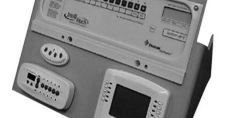
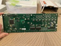
Hey guys, I have a Pentair Easytouch 4 system that had a bad LCD display screen in it and wanted to replace it with a white on blue display (wh1604a-tmi-jt). The bad LCD display didn’t affect the board as I can still turn on the relay circuits and be able to switch between modes so it still functioned normally. I desoldered the original LCD display and soldered in the new one, and once I got the motherboard connected back together again and turned the circuit breaker back on in my house to power the EasyTouch transformer, the screen lights up but nothing appears on the screen. None of the buttons or anything else responds on the board. I checked my multimeter and I got 10/18/24 volts on the transformer plug so I know the transformer is still giving out the correct voltage to it. I even tried just powering on the board with nothing else connected to it and just have the transformer plugged in only and still doesn’t boot up. Even worse, I desoldered the new screen thinking it might’ve been the culprit and put the old screen back in and when I try powering it on with the old screen, it doesn’t boot up either. So now I’m stuck with an EasyTouch board that doesn’t want to boot up and function anymore. I also checked my soldering pin connections that go from the LCD display to the board, and I made sure there are no shorts and it looked fine to me. Again, the transformer plug is giving out the correct voltage from my multimeter and I made sure all of the wires and connectors for the relays and the valves were in the right spot before when it was working and just trying to test the board with just the transformer plug only and nothing else connected and it still wouldn’t boot up. Do you think I messed up my EasyTouch board completely and need to get a new one? I’m not sure how my soldering messed it up as I only just replaced the LCD screen with the pin headers so I was a little bit surprised that it could be it as I have seen people replaced their LED screens on their EasyTouch boards and it worked fine for them with no issues. I have included pictures of my problem, as well as my soldering when I install the new LCD screen. Thanks!
IMG_6688.jpeg
IMG_6689.jpeg
IMG_6690.jpeg
IMG_6692.jpeg
IMG_6705.jpeg
 
I see that behavior when one of the control lines for the lcd isn't connected... usually this happens when I re-use a display that's been pulled off and one of the traces is damaged

But I know you soldered on a brand new display so all of those connections should be good... when you unsoldered it did you work the pins on the display side or on the bottom of the main board?
so when I was desoldering it, I mainly focused on the pins on the display side using low melt solder and hot air to remove it from the pins but I also put a bit more solder on the bottom of the board as well but none of them are touching each other or shorting out. Bear in mind I do have a lot of soldering experience, so I’m not a newbie at it.
 
have you got more than one spare display? or do you have an arduino or something you can use to verify the new display works?

when I'm working on a board that I pulled the display off of, I don't solder it back on until I've used a "test" display to verify that the board boots (these things won't start if the display isn't connected)... after I've cleaned and straightened the pins I temporarily fit my test display over the pins and pull up the bottom edge a bit, which usually puts enough pressure on all of the pins to make the display work - and the board boots. You could try that with a spare, OR you could also temporarily solder short wires from the board to the display - I've done this for testing as well because it's easier to remove the wires than de-solder a display if the display doesn't work or the board won't boot.
so the two displays that I have currently is the brand new white on blue one and the original display screen that wasn’t working properly that needed to be replaced but still powers on. When the white on blue screen didn’t boot up, I tried to put the old screen back on, and that wouldn’t work either despite having good solder connections but I think I know what you mean by testing it is to just have the display pins exposed, but nothing soldered onto it and just tried to get the board to boot by putting my white on blue display into the pins and bend it over a little bit and see if it boots? I’ve had a similar situation like this before where I had to put a circuit board over a pin headers and bend it slightly for it to work and to make the connections for testing before soldering it. Fyi, I also have to do this outside where the easytouch unit is because I don’t have an easytouch transformer inside which it’s not a problem for me.
 
you've got it exactly right!

and you can take the board inside and do it if you've got a 12v power supply... since you've got a hot air station I'd be willing to bet you've got a few power supplies ;)

you only need to connect 12vdc to the two 12vac inputs - don't need the others - and with nothing else connected to the board it'll draw ~200mA. see my post here on powering it from a power supply (oh, and the polarity doesn't actually matter because you're going through a bridge rectifier with dc... i should probably update that)

Gotcha, I do have generic 120v ac to 12v dc power supplies that plug into the wall, I don’t have a programmable lab station one (will have to get one soon), but for now I can just use the transformer in the easytouch panel outside to power the board. I just got the two screens desoldered so the holes are exposed and the easytouch board has the pins exposed with no screen soldered on it now. Right now it’s raining outside so I can’t go outside to test the board, but once it dries up I’ll plug the board back in and slide one of the screens onto the pins with it bent down slightly to make the connection and hopefully it should work right? I just don’t want to have to buy another board for $500 and I’m getting my hopes up that this can be repaired and working again since after all my passion is repairing and refurbishing electronics. I included pictures of the easytouch board and I don’t see any damage or issue that can be affecting it from booting up, but you can take a look and see if there’s an issue that you spotted.
IMG_6719.jpeg
IMG_6720.jpeg
IMG_6721.jpeg
IMG_6722.jpeg
IMG_6723.jpeg
IMG_6724.jpeg
 

Attachments

  • IMG_6718.jpeg
    IMG_6718.jpeg
    817 KB · Views: 2
  • IMG_6717.jpeg
    IMG_6717.jpeg
    665.9 KB · Views: 2
  • IMG_6716.jpeg
    IMG_6716.jpeg
    355.6 KB · Views: 2
  • IMG_6715.jpeg
    IMG_6715.jpeg
    526.5 KB · Views: 3
Hmm, I don't see anything obvious that looks wrong.

Did you pull the original header pins off and replace those too, or just add fresh solder to them?

What temp is your hot air gun set to? And I noticed in your first pic, the display spacers are missing... this isn't a big deal other than the display will be set back further behind the bezel.
I only added fresh solder to the pins (pre-tin), never been pulled out of the board since I don’t have replacement pin headers and there should be no reason to replace it. I had to cut off those nylon spacers that hold the old screen in order for me to remove it, I couldn’t remove it with those on there but I knew it wouldn’t be an issue since the solder will still hold onto it. I always set my hot air station to 400C and soldering station to 350C for any soldering or rework project.
 
  • Like
Reactions: ogdento

Enjoying this content?

Support TFP with a donation.

Give Support
Since it’s summer time and I live in Florida, this is the only time where we’re getting lots of rain from time and time so unfortunately I may not be able to go outside and test the board today but I’ll try tomorrow but since you mentioned earlier that I can use a 12V DC power supply I do have those generic ones that plug into the wall. I wonder if that will be safe to use just to test the board to see if it boots up inside?
 
you can check the voltage output with a multimeter - if it's a transformer based wall-wart, as long as it's less than ~16 volts you should be fine (it'll drop once loaded). if it's a switching or regulated supply it'll probably output exactly 12.

If you're nervous about connecting it to 12vdc, you could also use your meter to measure the current it draws when you turn it on... just to make sure it's not too much over 200mA (however, your new display likely has a much more efficient backlight so the total current draw may go down to 80-100mA)
I did find a generic 12v dc power supply that takes 2a max and what I can do is cut the barrel connector off and strip the cable to expose the pos and neg wire and connect it to the 12v two pin connector on the bottom of the board to give it power to test it. Want to make sure this power supply and what I’m doing will work fine before I attempt to do this.
IMG_6727.jpeg
IMG_6728.jpeg
 
@ogdento So this morning, I got a chance to go outside and test it. I was doing your method on getting the displays to come on by bending down on the pins to make the connection and unfortunately still didn’t work or made a difference. Both screen still light up with the two lines of squares present and no boot to the board just like if it was soldered. What else can we do?
IMG_6730.jpeg
IMG_6734.jpeg
IMG_6733.jpeg
IMG_6735.jpeg
 
It feels more likely that the displays are damaged than the board... I have a few dead displays that only show those two lines no matter what I do - and then I can pop a good display on the pins, give it a little pressure, and it works. I'm not saying it's not possible, but I've never damaged a main board when messing with the displays.

One thing that can happen with replacement displays is the contrast can be way off... which can look like there are a bunch of blocks enabled. Usually though you'll see ALL blocks are in a "dark" state, rather than just two rows, kindof like this (I even have some LCDs that are much darker - you can fix it by adjusting R37):
IMG_20240611_134509181~2.jpg

If you can, I would suggest you wire up the new display to an arduino or similar dev board to make sure it's working... you can hook it up using only 4 data wires instead of the normal 8 if that makes it easier (saves you from connecting 4 of the pins). Or you could get a new display and try that.
 
It feels more likely that the displays are damaged than the board... I have a few dead displays that only show those two lines no matter what I do - and then I can pop a good display on the pins, give it a little pressure, and it works. I'm not saying it's not possible, but I've never damaged a main board when messing with the displays.

One thing that can happen with replacement displays is the contrast can be way off... which can look like there are a bunch of blocks enabled. Usually though you'll see ALL blocks are in a "dark" state, rather than just two rows, kindof like this (I even have some LCDs that are much darker - you can fix it by adjusting R37):
View attachment 584350

If you can, I would suggest you wire up the new display to an arduino or similar dev board to make sure it's working... you can hook it up using only 4 data wires instead of the normal 8 if that makes it easier (saves you from connecting 4 of the pins). Or you could get a new display and try that.
Bear in mind the white on blue display is brand new and only been used to test the board so I can’t see why that brand new screen can be defective out of the box and the old screen would still work with the board before I took it out but was just having glitchy characters so it needed to be replaced but now both displays won’t boot the board up at all. I don’t have an Arduino or a similar board to test it. When you said about if the contrast is way off, would that also prevent the board from booting up or can you still use the board even if the contrast is way off? I can try adjusting the contrast while the board is powered up and see if that does something.
 
you'd still be able to use the board with the contrast being too dark

I agree with the idea that a brand new display shouldn't be broken, but other than a damaged main board I have no other explanation
 
This is more informational than anything...

These are "Hitachi 44780 compatible" character displays, and the "two rows of blocks" are basically what you get when the display is turned on but not yet initialized. On power-up, a working Easytouch board will briefly show the "2 rows" pattern before it shows "Auto" with the time/temp, etc... if for some reason the board won't boot, the LCD can continue to show the "2 rows" pattern (and sometimes it's totally blank with just the backlight on)

So your display is powering up, but for whatever reason it's not able to receive the commands to display anything (or the Easytouch isn't sending them).

If I loosely hold and LCD onto a working Easytouch board's display pins - enough to get it to power up and for the backlight to turn on, but not enough to get good connectivity on all pins - the Easytouch can't successfully get any data to (or from) it, and voila, I get the "two rows" pattern
IMG_20240612_104858604~2.jpg

If I shut the board off, apply more pressure, and power back up - it works fine.