fuse keeps blowing on Hayward swim pure salt water panel.

chris4150

0
LifeTime Supporter
Hello,
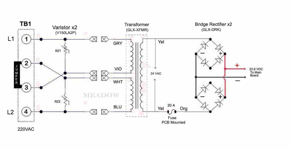
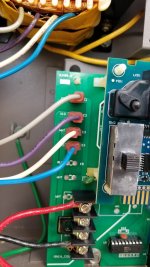
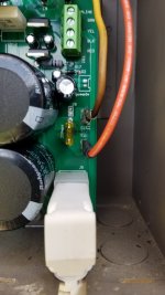
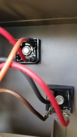
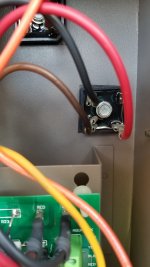
May salt water panel recently went dead, no lights, no power, no digital display etc. I replaced the black circular resister as previously in the past believing this was the issue and fix as previously. After swapping out the resister, I reinstalled the circuit board with all the wires in the right place and upon starting the pumps up and powering up the saltwater panel, I noticed that the resister did not fix the issue. I then removed the 20 amp yellow fuse and noticed that it was popped (black center). I then replaced the fuse with a new 20 amp yellow fuse and upon firing it back up, the fuse popped. I repeated this a total of two times with new fuses and each time it popped and the lights and digital display went blank. Any suggestions to the issue is greatly appreciated.
 
The 20A fuse protects the 24V circuit on the board. Blowing the 24A fuse says some component has probably burnt up and shorted out. You can carefully examine the board and components and see if you find anything.

Hayward Aquarite SWG - Further Reading has information about the board.

B&L Enterprises will repair Hayward boards if you are not comfortable doing board level repairs.

GLB-PCB-RITE_Low_Voltage_Power_Supply.jpg
 
Are you wired for 240VAC? Can you post a couple pictures of the mainboard? Assuming you did not disturb the bridge rects wiring, there is no reason for the fuse to get fused other than a short circuit. If you don't have access to a DVM, disconnect the RED and Black wires from the top right hand of the pcb. Install a known good fuse and turn on the AC power. If the fuse fused, one or both rectifiers had gone bad. If the fuse did not blow, inspect the pcb for short circuit. The last thing you fixed on the pcb is more likely the caused of the problem.
 
  • Like
Reactions: Hutchy
sorry for the late response. In reference to the responses of others,

The wires were all in the correct place on reinstall.
The salt water generator was clear of debri, no blown salt cell wire or burn marks.
I did have a pool tech come out and he tested the power and did show 24v return, so he has narrowed the issue to the main board.
I have ordered a new board and will be installing it this weekend. If this doesnt fix the issue, then its back to chlorine. :cool:
 
Are you wired for 240VAC? Can you post a couple pictures of the mainboard? Assuming you did not disturb the bridge rects wiring, there is no reason for the fuse to get fused other than a short circuit. If you don't have access to a DVM, disconnect the RED and Black wires from the top right hand of the pcb. Install a known good fuse and turn on the AC power. If the fuse fused, one or both rectifiers had gone bad. If the fuse did not blow, inspect the pcb for short circuit. The last thing you fixed on the pcb is more likely the caused of the problem.
After installing the new PCB, the 20 amp fuse still popped. I called the tech who verified the correct current from the transformer and he suggested that a ground short was the culprit and to check the red and black wires coming from the blocks on the back of the panel box. My replacement PCB did not come with the replacement wires for the red and black ones which Im being told is how the new PCB's are being shipped. Ill admit that the board was not an OEM, but a replacement for my particular brand of SWG. Any suggestions on where to get or create wire replacement? Ill check the wires as you previously suggested and see if the fuse still pops with the black and red wires disconnected.
 
I'll preface by stating that the yellow wire coming off of the transformer looks a little black at the rectifier. This occurred many years ago.
 

Attachments

  • 20210803_153718.jpg
    20210803_153718.jpg
    336.6 KB · Views: 29
  • 20210803_153702.jpg
    20210803_153702.jpg
    295 KB · Views: 21
  • 20210803_153658.jpg
    20210803_153658.jpg
    284.6 KB · Views: 21
  • 20210803_153652.jpg
    20210803_153652.jpg
    286.4 KB · Views: 25
  • 20210803_153639.jpg
    20210803_153639.jpg
    249.7 KB · Views: 28
  • 20210803_153630.jpg
    20210803_153630.jpg
    376.3 KB · Views: 31
  • 20210803_153619.jpg
    20210803_153619.jpg
    339.4 KB · Views: 48

Enjoying this content?

Support TFP with a donation.

Give Support
I don't think that there is anything special about the rectifiers.

You just need basic bridge rectifiers.

I think that something like the following should work.

Maybe someone else can confirm?


Mouser #: 583-MP356
Mfr. #: MP356
Mfr.: Rectron
Description: Bridge Rectifiers 35A 600V

 
Last edited:
  • Like
Reactions: Hutchy
I don't think that there is anything special about the rectifiers.

You just need basic bridge rectifiers.

I think that something like the following should work.

Maybe someone else can confirm?


Mouser #: 583-MP356
Mfr. #: MP356
Mfr.: Rectron
Description: Bridge Rectifiers 35A 600V

This is what I found on Amazon that had the wires with them. It also comes with fuses. What and where are these fuses being used?

 
The old gen Goldline AQR swcg use 20A glass fuse mounted at the bottom of the metal enclosure. The Red & Blk wires carries the electrical current from the bridge rects to the mainboard.
If you are not sure which one of the two rects went bad, then yeah go ahead and shotgun them. As JamesW mentioned earlier, there is nothing special about the bridge rectifier.

The original bridge rect is spec'd at 35A @ 400V. GBPC3504 TCI / TAITRON RECT BRIDGE GPP 35A 400V 2 PIECES | eBay
Or even better (35A @ 600V), 10 pcs for $10 10pc GBPC3506 Bridge Rectifier 35A 600V NEW | eBay

Use the existing Red & Blk wires or you can build your own if needed. Your local auto supply carries the spade connectors and 14 AWG wires. Cut to length and crimp. It is very important to follow the label or pin-out on the replacement bridge rect when connecting the wires. If in doubt, ask!
 
I noticed the yellow wires have burn marks at the connector side. It is a sign of high resistance connection and prone to failure. If I were you, I will cut the yellow wires at midway and make a pigtail with either butt connectors or bullet terminals and a spade connector on the other end. The choice is yours.
 
  • Like
Reactions: JamesW

Enjoying this content?

Support TFP with a donation.

Give Support
Thread Status
Hello , This thread has been inactive for over 60 days. New postings here are unlikely to be seen or responded to by other members. For better visibility, consider Starting A New Thread.