Determine Fan Speed without seeing it!

setsailsoon

Gold Supporter
LifeTime Supporter
TFP Guide
Oct 25, 2015
5,151
Palm City/FL
Pool Size
25000
Surface
Plaster
Chlorine
Salt Water Generator
SWG Type
CircuPool RJ-60 Plus
Folks,

*** Edited to provide a You-Tube link that should be helpful.***

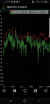
As some of you know I zapped my electronics to my Jandy pool using heater and can't seem to fix it. Everything points toward a problem with the fan speed. Since it's enclosed in a housing there's no way to use a light beam reflective type of rpm measurement. So I was thinking about using a Fourier's transform technique to calculate it. Thought I was in for a dive into my 45 old math books when I did a little Googling and found there's now an app for that! Yep, and it seems to work great. You download this app called Spectrum Analyzer App (I think there are a few other's that may work but I haven't tested them). Then you start the app with the fan running. In a few minutes you gather the spectrum data and can see the fundamental frequency in HZ. Divide by the number of blades (in my case 11) then multiply by 60 to get rpm. In my case the fundamental freq is about 430 (you can tell it's the fundamental frequency because there are repeated harmonics of this peak further on the right of the spectrum) then divide by 11 and multiply by 60 and I get 2345 rpm. Well below the rated speed of 3480 stamped on the motor. So something happened when I dumped a cup of water on the power distribution board right on the fan wires that messed the fan up too. Here's a You-Tube link that takes you to a demonstration of the technique. I've verified some of the measurements that he demonstrates with my android phone. Here's a screenshot of the spectrum that I used:

1573929830234.png

I have tried everything else that could be the problem and tested or replaced the components that proved defective. You can see the details of that in my heater repair thread. But I thought it would be better to put this thread up separately in case somebody searches for this with a more descriptive title. Moderator, if you'd rather put this somewhere else please do your magic and move to the appropriate spot.
I hope this helps somebody else.

Chris
 

Attachments

  • 1573929610687.png
    1573929610687.png
    84.8 KB · Views: 1
Last edited:
I'm not sure I would view that spectrum as being definitive. But isn't the blower motor an induction motor? If it was running that much lower RPM, it would heat up considerably. Is the motor running hot?
 
I'm not sure I would view that spectrum as being definitive. But isn't the blower motor an induction motor? If it was running that much lower RPM, it would heat up considerably. Is the motor running hot?

I agree but it does seem to be pretty close when I measure the pump speed. Everything I've tested has been within 200 rpm of rated speed. So it's definitely not perfect but the best way I can find. I'm sure it's an induction motor, and good point about the heating up. I'll check. I'm also not sure it would heat up if some of the winding was damaged causing the reduced speed. When it gets to this point everything gets a little iffy... frustrating. I'm also measuring similar resistance in both sets of winding on the motor. It has a 240 and 120 mode. One winding is reading 18.3 ohms the other is 17.6. Absolutely no way to determine what they should be. But I would think they'd be the same.

Many thanks for giving me another avenue. I've been down every road I can think of and I'm determined to make this bugger give it up sooner or later.

Chris
 
I'm not sure about the design of the motor, but I suspect that there are two sets of windings.

In a 120 volt configuration, the windings would be in parallel and the total resistance would be 1/R1 + 1/R2 = 1/Rtotal. Assuming that both windings are 18 ohms, the total resistance would be 9 ohms.

For a 240 volt configuration, the windings would be in series. Rtotal = R1 +R2 =36 ohms.

If the capacitor is in parallel with one set of windings, that will change the value of the reading.

If the motor uses a capacitor, try replacing it.

With the capacitor removed, check the resistance of the windings in a 120 and 240 volt configuration.
 
Last edited:
I think that the motor uses a capacitor. Try replacing the capacitor.
Already did that. Tested OK but it was cheap so I replaced it anyway. Didn't change anything.

Seems like the flame sense is not reading a good flame. The test points on the module definitely indicate a flame starts to ionize but it only gets to 150 mv before the 7 second timer shuts down the gas valve. The gas valve is new and I've verified inlet pressure and differential pressure (thanks to @swamprat for suggesting that to confirm gas supply). So I think the module is doing what it should do but I just don't have a big enough flame. The fire box is circular with the burner facing down in the middle. It's a tube about 3"wide with screen on the outside that lets the flame point out radially. The flame sense detector is in the top and only protrudes down about 2" inside the firebrick. So if the flame isn't high enough then the detector can't "see" it... at least that's my latest theory.

Any other idea's you can come up with would be very much appreciated.

Thanks.

Chris
 
I'm not sure about the design of the motor, but I suspect that there are two sets of windings.

In a 120 volt configuration, the windings would be in parallel and the total resistance would be 1/R1 + 1/R2 = 1/Rtotal. Assuming that both windings are 18 ohms, the total resistance would be 9 ohms.

For a 240 volt configuration, the windings would be in series.
James,
This is very helpful. I'm in 120 vac operation, tried 240 with no change. Still flames out in 7 seconds. I measure 18.3 ohms for one and 17.7 for the other. Does that make sense to you or is this enough to indicate winding damage?

Chris
 
The symptoms of the flame out point toward a gas injector orifice blockage (e.g. spider webs). Have you checked the nozzles for any blockage?
 
I'm not sure I would view that spectrum as being definitive. But isn't the blower motor an induction motor? If it was running that much lower RPM, it would heat up considerably. Is the motor running hot?
Mark,

I truly do appreciate anything you can offer to help. What should the temp be? It's about 75 here in FL. Here's a link on the spectrum analyzer approach. It's nowhere near as close as a good rpm gauge but I don't have that option. I've tested a couple of other induction motors around the house and it seems to be within 200 rpm. I did take the cover off the fan motor housing to count the blades. I have 11.

Thanks again for your help.

Chris
 

Enjoying this content?

Support TFP with a donation.

Give Support
A 2 pole 60Hz motor has a synchronous speed of 3600 rpm. A rated rpm of 3480 takes into account friction, load,slip etc.. If your calculations are correct you are only running at slightly over 2/3 of your rated rpm. I am trying to figure out what conditions would slow your blower down and still keep your full load amps well under the rating on the motor. Low voltage to the motor would decrease both efficiency and torque. I am assuming that the 5 wire harness to the motor is used because of the dual 120/240 v power supply choice from the board. I am also trying to figure out how the combustion blower can close the pressure switch running sat only 67% of its rating?
 
Check the resistance with the capacitor removed.

If the capacitor is in parallel with one set of windings, that will change the reading.
OK will do thanks. I'm detecting that when I check the resistance. It starts at zero then goes up to 18.2 in a few seconds. 18.2 on one and 17.6 on the other. I'll remove the cap and report back.

Many thanks.

Chris
 
A 2 pole 60Hz motor has a synchronous speed of 3600 rpm. A rated rpm of 3480 takes into account friction, load,slip etc.. If your calculations are correct you are only running at slightly over 2/3 of your rated rpm. I am trying to figure out what conditions would slow your blower down and still keep your full load amps well under the rating on the motor. Low voltage to the motor would decrease both efficiency and torque. I am assuming that the 5 wire harness to the motor is used because of the dual 120/240 v power supply choice from the board. I am also trying to figure out how the combustion blower can close the pressure switch running sat only 67% of its rating?
Great points you make. I wondered that as well. Seems that the pressure switch clicks immediately on start up. Maybe not so sensitive and just checking to see if the motor's running. Amp reading is well below the FL rating of .68. Runs about 0.4.

Please do keep coming up with ideas, I'm way out of my league!

Chris
 
If the flame rectification signal is not making it back to the Fenwal, then the unit will shut down.

Check the grounding of the burners and the Fenwal.
Thanks James, ran the traps on that and even ran an additional wire to the ground gang next to the fenwel from the closest connection to the burner tube. Also removed and cleaned all the ground wires to the firebox. This isn't a traditional heater with the burner at the bottom. The burner is concentric to the round firebox and gas-air is forced into it from the top then flows down the cylindrical tube to the bottom of the firebox. The tube is blocked at then end so the flame extends radially out from the cylinder that is screened on the outside of the cylinder and the water flow tubes are wrapped around the outside of the flame.

Hope that helps explain what I'm dealing with.

Chris
 
Folks,

Just so all of you helping know the background, the heater has worked virtually flawlessly for 5 years. And it gets a LOT of use. We swim year round and we start running the heater at least 2-3 times per week from now to March for at least the spa. I accidentally dumped a cup of water on the power distribution board and the universal control board when it was powered up with 240 v but not running. It popped and sparked with a vengeance! So anything weird could have happened. The boards all looked like they had forest fires on them so they've been replaced. The Fenwel also tested bad so replaced, same with the transformer. The motor ran so I thought it was good. Now the question is: at correct speed or not? Flame is not detected to be strong enough but it is detected. Gas supply and gas valve verified as good. So the only thing I can think of that would make the flame too small is the motor speed. Or a ground connection I've missed but I can't find one.

Hope this helps you help me and thanks to all for trying!

Chris
 
It popped and sparked with a vengeance! So anything weird could have happened. The boards all looked like they had forest fires on them so they've been replaced.

Chris, has EVERY electronic board in the heater been replaced?

Are there any electronics in the motor that could have gotten zapped or is the motor just dumb windings?

Just trying to help explore every path.
 
I'm not sure about the design of the motor, but I suspect that there are two sets of windings.

In a 120 volt configuration, the windings would be in parallel and the total resistance would be 1/R1 + 1/R2 = 1/Rtotal. Assuming that both windings are 18 ohms, the total resistance would be 9 ohms.

For a 240 volt configuration, the windings would be in series. Rtotal = R1 +R2 =36 ohms.

If the capacitor is in parallel with one set of windings, that will change the value of the reading.

If the motor uses a capacitor, try replacing it.

With the capacitor removed, check the resistance of the windings in a 120 and 240 volt configuration.
Thanks James, I checked with the capacitor disconnected and got the same readings about 17.6 and 18.3. Voltage starts at zero still then goes up to the resistance I've stated. Does this indicate there are internal capacitors?
 
Chris, has EVERY electronic board in the heater been replaced?

Are there any electronics in the motor that could have gotten zapped or is the motor just dumb windings?

Just trying to help explore every path.
Allen,

Anything you can think of is very much appreciated. Yes I've replaced all, the power distribution board, the universal control board, and the ignition module. They all appear to work as it goes completely through the start cycle including purge, pre-heat, opens gas valve, ignites then closes gas valve after 7 seconds.

Chris
 
Considering you said it It popped and sparked with a vengeance I would being closely examing the wires and connectors. It is a tedious job but checking continuity of each wire and connector. My thinking is maybe some wire has a loose pin or is hanging on by a few strands of copper.
 
  • Like
Reactions: setsailsoon

Enjoying this content?

Support TFP with a donation.

Give Support
Thread Status
Hello , This thread has been inactive for over 60 days. New postings here are unlikely to be seen or responded to by other members. For better visibility, consider Starting A New Thread.