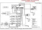
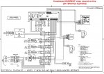
I need a little help with wiring in an accessory into my 1995 Hot Spring Grandee. The wiring diagram/schematic for the tub is below.
I'm going to install a system that will alow me to inject chlorine into the circ pump line via a wifi controlled switch which I can control remotely. After the chlorine is injected into the stream, I want to be able to circulate for a bit using the jet pumps which I also want to be able to turn off and on remotely. All I need to be able to do that is to put 12V DC to the 12V side of the non-ltatching jet pump relays so instead of those relays just being able to get 12V from the control board (top and says See Note 3 on the digram) they will also be able to get 12V from the wifi controlled switch when I activate it remotely.
I would like to put the +12V signals to the sides of the relays that gets the +12V signals from the control board and the negative to the negative. The problem is, I don't know what side of the relay that is but I'm not expert at reading these wiring diagrams/schematics. Is there any way to tell from the diagram? It may be difficult to tell from looking at the jet pump relays but it might be easier to tell or at least infer from looking at the circ pump and heater relays. All of the relays are identical so I'm assuming if they wire the 12V circuits on the circ pump and heater relays a certain way, they'll be consistent and do it the same way on the jet pump relays.
If there's no way to tell from the diagram, what is likely to happen if I guess wrong and wire them backwards? I'm thinking that in that case, when I put 12V to the relays from the wifi switch, the current will go straight to ground and will not latch the relays which is easy to test even with the tub drained and nothing powered up. Is that correct?
Can anyone help with this?
TIA
P.S. If I can get this remote controlled injection system working, I will look at taking the project further by adding in an Arduino or Raspberry Pi and an ORP probe to see if I can make a real low cost but reliable self monitoring/regulating chlorine injection system. That's a lot more complicated and a BIG challenge for me. Just getting this remote chlorine injection system working properly is a good but doable challenge for me to start out with and may be as far as I end up taking it.


