A little help with a wiring diagram needed

DangerBoy

Well-known member
Oct 4, 2018
167
Calgary/Alberta
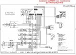
I need a little help with wiring in an accessory into my 1995 Hot Spring Grandee. The wiring diagram/schematic for the tub is below.

I'm going to install a system that will alow me to inject chlorine into the circ pump line via a wifi controlled switch which I can control remotely. After the chlorine is injected into the stream, I want to be able to circulate for a bit using the jet pumps which I also want to be able to turn off and on remotely. All I need to be able to do that is to put 12V DC to the 12V side of the non-ltatching jet pump relays so instead of those relays just being able to get 12V from the control board (top and says See Note 3 on the digram) they will also be able to get 12V from the wifi controlled switch when I activate it remotely.

I would like to put the +12V signals to the sides of the relays that gets the +12V signals from the control board and the negative to the negative. The problem is, I don't know what side of the relay that is but I'm not expert at reading these wiring diagrams/schematics. Is there any way to tell from the diagram? It may be difficult to tell from looking at the jet pump relays but it might be easier to tell or at least infer from looking at the circ pump and heater relays. All of the relays are identical so I'm assuming if they wire the 12V circuits on the circ pump and heater relays a certain way, they'll be consistent and do it the same way on the jet pump relays.

If there's no way to tell from the diagram, what is likely to happen if I guess wrong and wire them backwards? I'm thinking that in that case, when I put 12V to the relays from the wifi switch, the current will go straight to ground and will not latch the relays which is easy to test even with the tub drained and nothing powered up. Is that correct?

Can anyone help with this?

TIA

P.S. If I can get this remote controlled injection system working, I will look at taking the project further by adding in an Arduino or Raspberry Pi and an ORP probe to see if I can make a real low cost but reliable self monitoring/regulating chlorine injection system. That's a lot more complicated and a BIG challenge for me. Just getting this remote chlorine injection system working properly is a good but doable challenge for me to start out with and may be as far as I end up taking it.


1995 Grandee electric.jpg
 

Attachments

  • 1995 Grandee electric.jpg
    1995 Grandee electric.jpg
    382.1 KB · Views: 3
I don’t think polarity matters for a 12V DC relay to be energized. It should works wired either way.
 
There are a couple of ways of doing what you want, but to answer your question as asked,
I would like to put the +12V signals to the sides of the relays that gets the +12V signals from the control board and the negative to the negative. The problem is, I don't know what side of the relay that is but I'm not expert at reading these wiring diagrams/schematics. Is there any way to tell from the diagram?
Take a look at the relay schematics. You'll see the coil and outside the box you'll see a 0(zero) and a 1(one), the 1 is the positive side. You can also verify this by looking at the relays with the diodes across the coils. Those diodes are reverse biased (the cathode (-) is connected to the 12v positive side and the anode (+) is connected to the 12v negative side.

P.S. It can make a difference which way a DC component is connected. As for relay coils, some tolerate being connected either way, some just won't work when connected in reverse polarity. And, if you happen to have a relay with the diode paralleled to the coil, hooking it up in reverse will short circuit through the diode as now it'll be connected in the forward position.

As for contacts it really doesn't matter which way the current flows through the contact, but ideally it should be connected to flow in the N.O./N.C. and out the C terminal.
 
@Bama Rambler and everyone else who chimed in. Thanks! I hadn't noticed those 1s and 0s on the 12V leads to the relays in the schematic. But then again, I wouldn't have known what they meant so I learned something important and worthwhile today. It should be no problem to get things wired the right way now. :)?

I don't know if it would ever happen but I was curious to know what might happen if I got the polarity backwards on the wifi switch circuit and then if I ever activated that circuit to turn the pumps on while they were already on (i.e. if my neighbours were in using the tub (like they often do) and I was away somewhere and didn't know it and turned the pumps on remotely). In that case, I'd have 12V coming in on both sides of the relay at the same time. What would happen then? Would that cause the relay to unlatch and pumps to stop because there was no potential difference across the 12V side?

Now that my question has been answered, would people be interested in seeing how I go about creating and installing this low-cost remotely operated wifi enabled chlorine injection system I've schemed up? I can take photos and document the process here if people are interested. I think my total budget is going to be around or maybe a bit lower than $100 USD. If all works as planned, I should be able to inject known amounts of chlorine into the system and then "stir the tank" with the jet pumps from anywhere I can get an internet connection on my phone or tablet.
 
Last edited:
I don't know if it would ever happen but I was curious to know what might happen if I got the polarity backwards on the wifi switch circuit and then if I ever activated that circuit to turn the pumps on while they were already on (i.e. if my neighbours were in using the tub (like they often do) and I was away somewhere and didn't know it and turned the pumps on remotely). In that case, I'd have 12V coming in on both sides of the relay at the same time. What would happen then? Would that cause the relay to unlatch and pumps to stop because there was no potential difference across the 12V side?
IF you get the polarity backward and then fire the pump from both sources, hopefully all you'd do is blow a fuse. The worst that would happen is that you'd burn the main board out. You could also fry the transformer. Hopefully none of that happens.
 
Connecting backwards will blow something, the only question is what.
However, connecting the right way around could also cause damage, as you don't know what will happen when you apply 12v to the 'off' main board. Imagine for example that when off the board connects its output to ground, rather than floating - you'll have a short. At the very least, check with a meter, and even then it's still possible to break something.
A separate relay would be a safer bet.

Good luck with the project - I'm slowly creating something similar, using esp32 and a touchscreen, however without any manufacturer electronics to be compatible with other than heater and temp sensors.
 
@Jon_herefordshire

At first I didn't get what you meant when you said, "Imagine for example that when off the board connects its output to ground, rather than floating - you'll have a short." but I finally figured it out and I do agree that in that scenario I would have a short that could potentially damage my WiFi switch.

In order to mitigate that risk, could I not insert a diode in the circuit between the board and the jet pump relays so that when I apply 12V to the positive side of the relay, current can't flow back to the main board? I'm not an electrical engineer by any means but isn't a diode basically an electronic analog of a plumbing check-valve?

If that's a viable plan then by the same token I suppose I could put diodes on the positive signal wires going from the WiFi switches to the jet pump relays. That would protect the wifi switch from any potential damage caused by the pumps being turned on normally when the WiFi switches are off. Make sense?
 
Last edited:
Sorry, I didn't get an alert for some reason, just spotted this.

Yes, diodes to protect both circuits would probably do the trick. Not having seen it, I was imagining the relay was on the board and it wouldn't be possible.

There's a possibility that the main circuit wouldn't like it not being pulled down to zero, but it's much less likely to cause damage.

@Jon_herefordshire On this old tub the relays are just mounted on a panel and are connected to the board with wires so it's easy to insert diodes between the board and the relays. I bought some 400V 1A diodes to try. I can't imagine that a control signal to flip a relay would exceed 1 Amp so I think those diodes should suffice. Agree?
 

Enjoying this content?

Support TFP with a donation.

Give Support
Thread Status
Hello , This thread has been inactive for over 60 days. New postings here are unlikely to be seen or responded to by other members. For better visibility, consider Starting A New Thread.