- Jul 21, 2013
- 65,340
- Pool Size
- 35000
- Surface
- Plaster
- Chlorine
- Salt Water Generator
- SWG Type
- Pentair Intellichlor IC-60
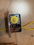
Would it be okay to wire it 115v, and use the intermatic T101, and then follow your directions? Is it ok to wire 2 devices (pump and SWG power center) to the load terminals?
I will tell you that is not to current National Electric Code (NEC). However many folks have it wireed that way and it works.
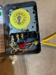
You can put two wires on the load terminals ok. Alternatively you wire nut the two or more wires together with a short pigtail wire that you connect to the load terminal.