Yet another toggle switch wiring thread

Hi All,
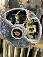
Sorry to ask this, but I couldn't find the exact circumstance in my search of this topic and just want to be sure before I connect a toggle switch to our A.O. Smith 2 speed pool pump motor...

The slight difference between what I've read and my situation is that the 220v wiring from the panel to the pump was done a long time ago -- meaning, two hot (in this case red) leads and a white "neutral/ground" wire. Also, the toggle switch (rated for 15 amps, 240 volts) has 3 tabs but no leads on them right now.

I have included the label from the motor, and if I have figured this out correctly, I will:

  • Connect one of the hot leads to the #1 connection on the back of the motor.
  • Connect the other hot lead to the middle tab on the toggle switch (where the black wire comes out in the switches that already have leads attached, call it #2 on the switch).
  • Run a short piece of yellow wire from one of the end tabs on the switch (either 1 or 3) to the connector labeled #2 on the back of the motor.
  • Connect the white wire from the breaker box to the #3 or #4 connector on the back of the motor and also run a short piece of white wire from the remaining end tab on the toggle switch (1 or 3) to #3 or #4 on the back of the motor
This last connection (the white wire from the breaker box and the white wire from the toggle switch) has me the most confused... should I NOT run the white "ground/neutral" in this situation to the motor at #3 or #4, but instead ONLY run a short lead from the back of the toggle to #3 or #4 ? If that is the case, should I run the white wire from the breaker box to the ground connector on the back of the motor? My increasingly faulty memory is telling me that when it was wired without the toggle switch, it was simply one hot line to #1 on the motor, the other hot line to #2 on the motor, and the white wire was tied to the ground terminal. Hopefully, that was correct, because it ran that way for years :)

Any advice will be greatly appreciated !

Thanks,
David
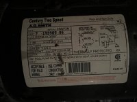
AO Smith wiring diagram.jpg
Back of AO Smith motor.jpg
 
David,

  • Connect one of the hot leads to the #1 connection on the back of the motor.
  • Connect the other hot lead to the middle tab on the toggle switch (where the black wire comes out in the switches that already have leads attached, call it #2 on the switch).
  • Run a short piece of yellow wire from one of the end tabs on the switch (either 1 or 3) to the connector labeled #2 on the back of the motor.
Up to here is just fine.
  • Connect the white wire from the breaker box to the #3 or #4 connector on the back of the motor and Do not do this!!!

  • run a short piece of white wire from the remaining end tab on the toggle switch (1 or 3) to #3 or #4 on the back of the motor
Basically, L2 comes into the common pin on the switch and the switch either sends the L2 voltage to the High Speed Pin #2 or the Low speed Pin #3/4

The only thing you are missing is the ground. 240 volt pumps do not get a Netural wire.

Thanks,

Jim R.
 
Be very careful. Your motor (in very bad condition) is a 240v motor. The white is NOT a neutral. It is one of the 120v legs to the pump motor, the common and will be "hot" if the breaker/timeclock is on. It goes to terminal 1 in the motor. (White is usually only used in a 4-wire installation, not a 3)
A wire from the other side of the breaker/timeclock will go to the common (center?) terminal on the double-throw single pole toggle switch. A wire from one of the terminals from that switch will go to 2 in the motor and another from the other the terminal that is left to terminal 3or4 in the motor (that's how it is labeled).
 
David,

The pump only needs to get L1 and L2 to run. You need to test between the two red wires and make sure you get 240 VAC.

The color of the wire is not important. What is important is that it needs to be a ground wire and not a neutral wire.

Obviously, if we were doing this new, we'd use the correct colors. But with old systems you sometimes have to use what is there (color wise).

If the white wire is actually a Neutral wire, do not connect it to the pump.

Thanks,

Jim R.
 
Hi Jim, 1,
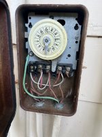
Thanks very much for your replies -- I appreciate them !!! I am really embarrassed to say that the third wire is NOT white, but a very badly faded green (ground) wire. Below is a picture that I took after reading your responses...
So let me try this again, after getting your excellent advice:
  • Connect one of the red (hot) leads from the clockswitch to the #1 connection on the back of the motor.
  • Connect the other red (hot) lead from the clockswitch to the middle tab on the toggle switch (where the black wire comes out in the switches that already have leads attached, call it #2 on the switch).
  • Run a short piece of yellow wire from one of the end tabs on the switch (either 1 or 3) to the connector labeled #2 on the back of the motor.
  • Run a short piece of white wire from the remaining end tab on the toggle switch (1 or 3) to the #3/#4 on the back of the motor
  • Connect the green ground wire from the clockswitch to the grounding terminal on the motor.

Thanks Again,
David

Clockswitch.jpg
 
Thread Status
Hello , This thread has been inactive for over 60 days. New postings here are unlikely to be seen or responded to by other members. For better visibility, consider Starting A New Thread.