This is going to sound like a dumb question.
I am looking to add a couple of solar panels to supplement ( mostly replace) my grid power to the pump. I also have the Easy Touch 8. First a little background on the solar set up and the issue the pump creates.
I will be using about 600 watts of solar with enphase micro inverters which will provide power to the pump. The inverters will back feed the grid with any excess power that pump is not using which is fine but i don't want it to ( another story for another time ).
).
To do this with a dumb pump and or mechanical timer is straight forward. Solar wires go to the the load side of the relay/ switch and when the timer shuts off the micro inverter stops sending power as it needs to sense grid power to allow its power to flow.
The issue: As some of you already know, the intella flow is supposed to have power all the time, hence it is hooked to the line side of the easy touch relay. On my system there are also addtional wires coming off the pump relay which go to the heater but also to the transformer.
I could hook the solar to the line side ( which will isolate the micro inverter as intended) but I am not sure power would ultimately reduce the incoming grid needed when the pump is running which is the goal.
Obviously the Intella flow is intended to have power all the time. What happens if I hook it up on the load side of the relay and it does not?
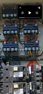
I am ok with loosing the benefit of the variable speed if needed. Long way to go to get to the question, but I wanted folks to understand what I am trying to do. I have attached a picture just for kicks. Blue wires are from pump and breaker. Smaller yellow go to heater and and larger yellow and white wires go to the transformer.
Thanks for any input you have to offer!
I am looking to add a couple of solar panels to supplement ( mostly replace) my grid power to the pump. I also have the Easy Touch 8. First a little background on the solar set up and the issue the pump creates.
I will be using about 600 watts of solar with enphase micro inverters which will provide power to the pump. The inverters will back feed the grid with any excess power that pump is not using which is fine but i don't want it to ( another story for another time
).To do this with a dumb pump and or mechanical timer is straight forward. Solar wires go to the the load side of the relay/ switch and when the timer shuts off the micro inverter stops sending power as it needs to sense grid power to allow its power to flow.
The issue: As some of you already know, the intella flow is supposed to have power all the time, hence it is hooked to the line side of the easy touch relay. On my system there are also addtional wires coming off the pump relay which go to the heater but also to the transformer.
I could hook the solar to the line side ( which will isolate the micro inverter as intended) but I am not sure power would ultimately reduce the incoming grid needed when the pump is running which is the goal.
Obviously the Intella flow is intended to have power all the time. What happens if I hook it up on the load side of the relay and it does not?
I am ok with loosing the benefit of the variable speed if needed. Long way to go to get to the question, but I wanted folks to understand what I am trying to do. I have attached a picture just for kicks. Blue wires are from pump and breaker. Smaller yellow go to heater and and larger yellow and white wires go to the transformer.
Thanks for any input you have to offer!