Wiring for Intermatic T104 with external override switch

Atenas2007

Member
Dec 20, 2020
7
Atenas, Costa Rica
My pump went dead. I hoped that it was a bad timer switch and replaced the Intermatic T104. Still dead. I then called a local pool guy. We decided that the huge scorpion that was across capacitor contacts might have had something to do with the failure. Pool guy replaces capacitors and rewires the T104 timer and pool works great - except my remote override switch has been disconnected. I have the switch wires suspended in space at the moment.

My pool has two “infinity” sides. Swimming laps without the pump running dumps out a lot of water eventually making it choppy. While the T104 does have a manual override, it is past a gate, down some stairs through a locked door into a bodega/pump room. Not what you want to do for a quick swim. For that reason, I have a remote manual override switch poolside. Worked great before the scorpion committed suicide in the pump motor.

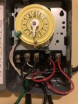
Now the question. On the standard T104 timer, what two terminals do I attach the override switch?
 

Attachments

  • Intermatic-t104-240V.pdf
    212.8 KB · Views: 11
Show us pics of the wiring inside your T104.

Is your pump 120V or 240V?

What model pump do you have?
 
The T104 timer has the standard wiring per the attached - with the two wires from the remote pump dangling at the moment. The pump is a Gould 240V JRS 10 jet pump with a Hayward label on it. Any guidance on which terminals to attach them to appreciated.
 

Attachments

  • Intermatic-t104-240V.pdf
    212.8 KB · Views: 17
Two wires on a switch are normally used for 120V. Four wires are normally switched for 240V.

Something does not make sense and may be why your pool guy did not connect it.

Show us pictures of the actual T104 timer wiring and of your override switch.
 
Probably overkill on the pictures. Yes indeed, my remote override switches has two pair that run into it. (I also just replaced the switch out of an abundance of caution.). When those two pair get to the equipment bodega, they are spliced into one cable and thus two wires - that you can see in front of the timer. This system worked just fine for a decade, but what has been lost is picking the terminals on the timer for connection. Thus, two of 1,2,3,4?
 

Attachments

  • EC7CACC5-91E4-4FF8-8DBF-611A726C4096.jpeg
    EC7CACC5-91E4-4FF8-8DBF-611A726C4096.jpeg
    368.7 KB · Views: 17
  • 58E5F60D-34C3-42CD-ADDB-C43A8E1BDA12.jpeg
    58E5F60D-34C3-42CD-ADDB-C43A8E1BDA12.jpeg
    369.4 KB · Views: 18
  • E89DB66E-D717-447D-8FA7-AD969DF4373E.jpeg
    E89DB66E-D717-447D-8FA7-AD969DF4373E.jpeg
    254.2 KB · Views: 16
  • A26A1698-794D-4D6F-98E7-AE52D83EBF7A.jpeg
    A26A1698-794D-4D6F-98E7-AE52D83EBF7A.jpeg
    265.3 KB · Views: 13
Tell me the manufacture and model number of the switch or post a clear pic that I can read the writing on the back of the switch.

154091-11266430f044c0e6f641b208ca6b98ce.jpg


It should be simple to wire this switch if you have a basic knowledge of electrical wiring. The fact that you need to ask here says you need to get very specific advice.

When those two pair get to the equipment bodega, they are spliced into one cable and thus two wires

Explain this more as it will take 4 wires and 4 connections to override the timer.

Intermatic T104 Wiring.png

The override switch needs to connect 1 to 2 and 3 to 4 to complete both legs of the circuit and turn the pump on.
 
Last edited:
Thanks for your reply. Sorry, wiring the switch is not the issue. It is where on the timer, the leads from the switch should be connected.

The answer is in the wiring diagram above if you think you understand how your override switch works. I don't.
 
Thread Status
Hello , This thread has been inactive for over 60 days. New postings here are unlikely to be seen or responded to by other members. For better visibility, consider Starting A New Thread.