Wiring Check of my Mechanical Timer

manthemike12

Bronze Supporter
Jul 20, 2021
25
Boston, MA
Pool Size
18000
Surface
Plaster
Chlorine
Salt Water Generator
SWG Type
Pentair Intellichlor IC-40
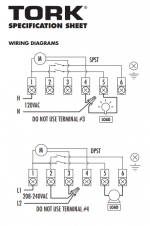
I'm replacing the mechanical timer for my pool equipment. The replacement model is a Tork 1109A-O. I have attached the below wiring diagrams.
I have my line and then will have two loads from the timer.
Load A: VS Pump. I want this to always be on. The pump has a schedule set in the control panel
Load B: SWG. I want this switched by the mechanical timer.
Pump: Pentair - EC-011028 230V
SWG: Pentair - EC-520555 - IC40

Based on the VS Pump being 230V would I have to use the DPST config?
If using the DPST config, would I wire the VS Pump to Terminal 1 (Hot) and then the neutral with the other neutrals in the wire nut?
tempsnip.png
 
Yes you would use the DPST diagram.
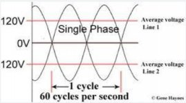
If you want the pump to be energized all the time and use the VSP panel to control pump operation, you would connect to L1 & L2, you have a couple of choices on how to accomplish this, you can connect to terminals 1 & 2 or 1 & 3, or terminal 1 and the wire nut (208/240VAC there is no neutral, in this diagram both L1 & L2 are both hot 120V lines, on opposing cycle curves so while L1 is 120V positive, L2 is 120V negative, the differential between the two is 240V)
2023-05-08_9-11-00.jpg
If your SWG is set up to run on 208/240VAC, you would connect it to terminals 5 & 6, if it's set up for 120 VAC, you would be better to rewire for 208/240VAC operation.
 
  • Like
Reactions: manthemike12
Mike,

You'd use the bottom (240 volt) diagram.

The SWCG would be connected to pins 5 and 6. (Make sure to use the 240 Volt wires for the SWCG)
The VS pump would be connected to pins 1 and 2.

This is the same thing that drsipe said, I was just confirming it.

Thanks,

Jim R.
 
  • Like
Reactions: drsipe
Yes you would use the DPST diagram.
If you want the pump to be energized all the time and use the VSP panel to control pump operation, you would connect to L1 & L2, you have a couple of choices on how to accomplish this, you can connect to terminals 1 & 2 or 1 & 3, or terminal 1 and the wire nut (208/240VAC there is no neutral, in this diagram both L1 & L2 are both hot 120V lines, on opposing cycle curves so while L1 is 120V positive, L2 is 120V negative, the differential between the two is 240V)
View attachment 489633
If your SWG is set up to run on 208/240VAC, you would connect it to terminals 5 & 6, if it's set up for 120 VAC, you would be better to rewire for 208/240VAC operation.
Ah this makes sense now! I've really only done outlets, switches and lighting in my home so now I see how 240V is different. It makes sense why the wires are Red and Black instead of Black and White, as both are "hot". I find electrical fascinating, I should really see if there are part time classes I can take.
I'll do Term 1 and 2 approach.
 
  • Like
Reactions: drsipe
Thread Status
Hello , This thread has been inactive for over 60 days. New postings here are unlikely to be seen or responded to by other members. For better visibility, consider Starting A New Thread.