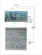
I recently purchased a toggle switch end cap from INYO pools. The wiring schematics we awful. Problem is I have four wires coming from my Intermatic 104 timer. Two hot wires. I know where the Black one goes. I have included a wiring diagram. If the red wire goes to L2 COM. Where does the neutral white wire from the timer go?

Wiring a Toggle Switch.
- Thread starter David70
- Start date
You are using an out of date browser. It may not display this or other websites correctly.
You should upgrade or use an alternative browser.
You should upgrade or use an alternative browser.
David,
You don't have a Neutral for a 240 volt pump.
The Green wire goes to where it say "Green Ground".
Thanks,
Jim R.
You don't have a Neutral for a 240 volt pump.
The Green wire goes to where it say "Green Ground".
Thanks,
Jim R.

Hi Jim. So the red wire goes out o L2 COM and I disconnect the white wire coming from the neutral screw on the timer.David,
You don't have a Neutral for a 240 volt pump.
The Green wire goes to where it say "Green Ground".
Thanks,
Jim R.
- Feb 6, 2015
- 7,813
- Pool Size
- 12300
- Surface
- Plaster
- Chlorine
- Salt Water Generator
- SWG Type
- CircuPool RJ-45 Plus
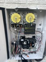
Post a pic of the inside of the timer with the wire connections showing.
Is the pump using 120vac or 240vac?
The image you posted showing the black and red wires connected with a wirenut is incorrect - if following standard wire colors.
Is the pump using 120vac or 240vac?
The image you posted showing the black and red wires connected with a wirenut is incorrect - if following standard wire colors.
Last edited:
David,
One of your hot leads (L2) goes directly to Com/L2
The other hot lead (L1) goes to the com input to the switch (yellow/black)
The white switch outputs goes to Low A
The yellow switch output goes to High L1
The Green wires goes the Green Ground not where your drawing shows it.
Basically, the pump sees L2 all the time.
It sees L1 on the Lo pin and then the pump runs at your low speed.
When you move the switch, it then see L1 on the High pin and the pump runs at full speed.
The pump does not use the neutral wire.
Thanks,
Jim R.
Post a pic of the inside of the timer with the wire connections showing.
Is the pump using 120vac or 240vac?
The image you posted showing the black and red wires connected with a wirenut is incorrect - if following standard wire colors.
Attachments
Thank you sir.David,
One of your hot leads (L2) goes directly to Com/L2
The other hot lead (L1) goes to the com input to the switch (yellow/black)
The white switch outputs goes to Low A
The yellow switch output goes to High L1
The Green wires goes the Green Ground not where your drawing shows it.
Basically, the pump sees L2 all the time.
It sees L1 on the Lo pin and then the pump runs at your low speed.
When you move the switch, it then see L1 on the High pin and the pump runs at full speed.
The pump does not use the neutral wire.
Thanks,
Jim R.
hi Jim one other question. My current setup with out the switch. There is a white wire rumming from the Neutral on the timer to COM on the pump. So your saying the white wire isn’t necessary?David,
One of your hot leads (L2) goes directly to Com/L2
The other hot lead (L1) goes to the com input to the switch (yellow/black)
The white switch outputs goes to Low A
The yellow switch output goes to High L1
The Green wires goes the Green Ground not where your drawing shows it.
Basically, the pump sees L2 all the time.
It sees L1 on the Lo pin and then the pump runs at your low speed.
When you move the switch, it then see L1 on the High pin and the pump runs at full speed.
The pump does not use the neutral wire.
Thanks,
Jim R.
David,
The color of the wire does not really mean anything as you have no clue who wired it. White "should" be a neutral wire but many times is is not.
You can't just trust the colors, you need a voltmeter so that you known what your inputs are..
If your old pump had a white wire going to it, it was either a 120 pump OR it was wired with the wrong color wires, which very common to see...
Do you have a voltmeter?
Thanks,
Jim R.

Yes I do.David,
The color of the wire does not really mean anything as you have no clue who wired it. White "should" be a neutral wire but many times is is not.
You can't just trust the colors, you need a voltmeter so that you known what your inputs are..
If your old pump had a white wire going to it, it was either a 120 pump OR it was wired with the wrong color wires, which very common to see...
Do you have a voltmeter?
Thanks,
Jim R.
This is my current set up and the pump does rum but only on low speed.Yes I do.
Attachments
David,
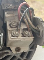
In your current set up, take your voltmeter and measure between the White wire (common) and the Red wire and see what you get.
You should get 120 if you have a 120 volt 2-speed pump, or 240, if you have a 240 volt 2-speed pump.
Then measure between the White wire and the Black wire and you should get zero volts. This is because whatever is switching your pump to high speed is not working, or at least not switched to high speed.
If it were working, when you switched to high speed, the Black wire would have voltage and the Red wire would not. You can NEVER have voltage to both the Low speed input and the High speed input at the sametime.. Unless you like a lot of smoke..
Please let me know what you get.
Thanks,
Jim R.
Thanks Jim. It hit me that hat you were talking about. Yes the guy that originally installed the pump used White as one of the lines. I switch it Red. I now have a functioning Hi/Low switch for my pump. Timer and switch function properly. Thank you for your help.David,
In your current set up, take your voltmeter and measure between the White wire (common) and the Red wire and see what you get.
You should get 120 if you have a 120 volt 2-speed pump, or 240, if you have a 240 volt 2-speed pump.
Then measure between the White wire and the Black wire and you should get zero volts. This is because whatever is switching your pump to high speed is not working, or at least not switched to high speed.
If it were working, when you switched to high speed, the Black wire would have voltage and the Red wire would not. You can NEVER have voltage to both the Low speed input and the High speed input at the sametime.. Unless you like a lot of smoke..
Please let me know what you get.
Thanks,
Jim R.

Thread Status
Hello , This thread has been inactive for over 60 days. New postings here are unlikely to be seen or responded to by other members. For better visibility, consider Starting A New Thread.