Weird electrical thing, figuring out solutions

superdave5599

Well-known member
Mar 20, 2023
250
Wamego, Kansas
Pool Size
30000
Surface
Vinyl
Chlorine
Salt Water Generator
SWG Type
CircuPool Universal40
Bought house in December, still figuring out all the pool stuff.

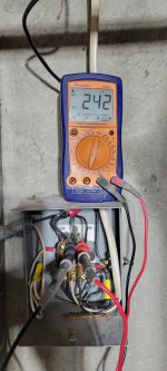
One thing that has/had vexed me is this electrical box. Is fed by the circuit panel. I even had a guy out and he couldn't tell me for sure what it was doing. (He was doing a quote for replacing my old stab-lok style panel. As I have been thinking about it this morning, it is entirely possible that the quote guy they sent may or may not be an electrician...)

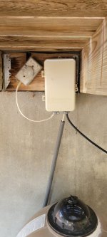
Anyway, power goes from the circuit panel (one 15 amp breaker and one 20 amp breaker) into this box. There is a momentary switch on the side of the box. When you push the momentary switch, the magnetic coil is energized to close the connection. And it is kept closed by the power/connection itself being made. Stays connected until, for whatever reason, power is cut to the box. From the box, a single cable goes to the exterior of the house, into a not-great junction box outside, then into the timer, and from there the pump and SWG.

I took another, closer look at the insides of the box this morning. I think what it is doing is combining the two 110v breakers to make a 220v circuit to feed the timer and pump. Looking closely at the Romex cable, I am certain it is 12g wires. It is stamped, not printed but it looks like larger than 14g and I am certain I saw 12 on the jacket. I think the pool setup is old enough that the wiring was done before the jackets were color coded to yellow for 12g.

This is all well and good except for two things:
First, there is not yet any GFCI protection. I was originally thinking I had 120v going to the exterior (based on looking at the jacket before investigating deeper today) and was just going to install a GFCI outlet in that junction box. But now I don't think I can do that.

Second, if there is any sort of blink in power, the electromagnetic connection is broken and power is cut off to the pump and SWG. This happened Saturday night (we were driving home and saw the power blink as we approached a stoplight near the house) and I didn't even think about the electromagnetic connection being broken until I went to manually run the cleaner Sunday evening. Thankfully I went to do that, because it may have been several days otherwise.

That isn't necessarily a giant deal, except for if I don't notice it, or maybe it happened while we were on vacation. We're going to be gone Friday to Monday this weekend.

So that got me to thinking about other remedies.

Looking at the label on my pump, it appears it can be wired to operate off of either 110 or 220. I was thinking I could swap the wiring on the motor and run everything off of one 110 circuit breaker and install a GFCI outlet like I'd planned. But it appears the timer motor only runs on 220 (just looked at a pic I snapped a few weeks ago of the inside door of the timer). Blast!

I suppose I could still do the wiring changes and update the timer to one that would work with 110v?

Or, I do see I could get something like this to add GFCI protection.

The timer and the exterior junction box are under my deck and only accessible outside the pool area which makes things like manually turning the pump on and off to vacuum or empty the skimmer basket inconvenient, so I had been thinking of relocating everything to be inside the pool area.

One benefit of switching everything to 110v is then I could use one of the two pool breakers to run a more proper circuit to my garage, which would be super handy because it is also lacking at the moment. I see that there are actually GFCI breakers available for my stab-lok box, so I could either add GFCI there or by an outlet sending power to everything. (Is the breaker any better/safer than an outlet for any reason, there is a significant price difference.)

Are there any real drawbacks to wiring the pump to run on 110v? I do recall asking a friend about 110v vs. 220v on my air compressor and he said that it will consume more power at 110v. True? How much more? I wasn't worried about that with the air compressor, but it does seem like a consideration with the pool pump.


Do my suspicions of what this box is doing (taking two 110v circuits to make one 220v circuit) seem correct?

What are my real options to improve all this (e.g. adding GFCI and not having to worry about power accidentally getting cut and not realizing it) without spending an arm and a leg for a full panel replacement at this time? (I would like to have that done at some point down the road.)

Second pic is just the label on the electromagnetic device.

20230523_061744.jpg20230523_061825.jpg20230523_063314.jpg20230421_213242.jpg
 
Just had another thought:

Perhaps I could change the box next to the panel to something like a sub panel, where the two breakers still feed it, but they feed a 220v GFCI breaker instead of the electromagnetic switch?
 
Dave,

Show us a pic of the two breakers being used to supply power to your contactor (relay) box.

If you want to get rid of the contactor, all you need to do is move the two hot output wires from the bottom pins and connect them to the two hot input wires on the top pins. This would remove the relay and the switch from the circuit.

Do you have a voltmeter? If so measure between the top center connection and the top right connection and see what voltage you have. I assume it will be 240 volts, but we need to know for sure.

Thanks,

Jim R.
 
Nothing super special. Position 13 and 14 (in this pic flipped to off) are marked for the pool. This pic was taken before I opened the pool.

But the hot lead from each breaker leads into the box with the contactor, which is right next to the main panel.

20230408_143703.jpg
 
Looking at the pic of the contactor box, assuming my suspicions are correct that this is being used to send 220v to the pump, etc., is it correct that the 3rd wire is bare and going to ground rather than insulated and going to neutral?
 
The advantage of 240 vs 120 is that it takes 1/2 the current to deliver the same amount of power down the wire, which means 1/2 as much power lost in heating the wires (for a given size of wire). For things with very heavy starting current like air-compressors, or HVAC compressors this helps a lot with that initial startup. For a pool pump (particularly a modern VS pump) this is much less of a concern. If were me I would probably leave it as a 240V connection however.

Hard to tell what the intent of the relay was, perhaps the previous owners didn't want the the pool pump to resume it's operation automatically after a power failure, or perhaps that relay was used in some more complicated way in the past. In any event removing it from the equation is as simple as Jim suggests. I would probably wire-nut the two black wires coming in from the panel directly to the White & Black of the cable leading to the pump, and remove all the other connections to the relay. (Note that the using 12/2 cable for a 240 V feed is one of the exceptions in the electrical code where a white wire is allowed to be "hot".)

If you do keep the system at 240V, then you should replace circuits 13,14 in your main panel with a single two pole breaker. The arrangement with two separate breakers does not meet code and is potentially hazardous (the equipment will appear to be off but there is still live voltage present). It also should be a GFCI breaker. If you go ahead with replacing that main panel, then you electrician can probably take care of that for you.
 
Looking at the pic of the contactor box, assuming my suspicions are correct that this is being used to send 220v to the pump, etc., is it correct that the 3rd wire is bare and going to ground rather than insulated and going to neutral?
Dave,

I have no clue what that means... :scratch:

There are two black and one white wires coming in the from the left side of your pic.

The white wire, which I assume to be a neutral wire from the main breaker box, is only being used for the circuit that turns your contactor (relay) on and off.

The two black wires, I assume are two hot wires coming into the contactor. The question is what is the voltage between them. I need to know before I can move forward. Do you have a voltmeter, and can you measure between the top center contact and the top right contact and see what the voltage is?

Does the white cable going out the top of your pic go to your timer or does it go to your pump?

Thanks,

Jim R.
 
I'm having a hard time finding a
Dave,

I have no clue what that means... :scratch:

There are two black and one white wires coming in the from the left side of your pic.

The white wire, which I assume to be a neutral wire from the main breaker box, is only being used for the circuit that turns your contactor (relay) on and off.

The two black wires, I assume are two hot wires coming into the contactor. The question is what is the voltage between them. I need to know before I can move forward. Do you have a voltmeter, and can you measure between the top center contact and the top right contact and see what the voltage is?

Does the white cable going out the top of your pic go to your timer or does it go to your pump?

Thanks,

Jim R.
Yes, I can measure the voltage this evening. But you assume correctly, the neutral wire you see is coming from the main breaker box and providing neutral for the contactor only.

The furthest left connection seem to be to make the contactor itself lock in place until power is cut (that power is tied to the 15 amp breaker). The middle and right are connecting a conductor from each of the breakers in the panel to the conductor in the white cable.

That white cable that exits the top of the contactor box does go the to pump timer.

If we assume that the power between the two connections (top middle and right) does equal 220v as it seems it probably does:

It seems like the most cost effective way to get rid of that connector and add a GFCI to the power would be to rewire the pump to run on 110 and buy a timer and GFCI outlet to correspond to 110v. That could hold off until I can afford to have the whole panel replaced (I am aware of the concerns about the FPE boxes and stab lok breakers). And most timers would be an operational upgrade to what I have now.

And, I'd have the bonus of being able to use the other breaker to run power to the garage!

But, I am certainly open to other ideas that I may not be considering.

It doesn't seem like a two-pole GFCI breaker is readily available. Only option I could find would be $750! And I don't really want to throw that at the panel I hope to replace in the near-ish future.
 
After doing a bit of google searching I can see why you would be considering replacing that stab-lok panel. While breakers are available I was unable to locate any 2-pole GFCI breakers as would be suitable for feeding your pool equipment. If you go down that road I would also recommending upgrading your utility service to 200A from 100A.

A lower-cost option would be, as you thought, install a modern 60-70 Amp sub-panel along side the main fed by a breaker in the 13/14 location, then in that subpanel install the 20A GFCI 2-pole breaker for your pool equipment as well 20A single-pole breaker as the "better circuit" for your garage.

Can you provide a wider pictures of both the basement area where the main panel and the relay box are, and the exterior area where your timer is? As well as maybe a picture of your equipment pad? That will help us get a better picture of what you are dealing with. In particular if that 12-2 romex is exposed on the exterior, that is a code no-no. (But if it comes directly through the wall and into the back of the timer box, that's probably ok.)
 

Enjoying this content?

Support TFP with a donation.

Give Support
After doing a bit of google searching I can see why you would be considering replacing that stab-lok panel. While breakers are available I was unable to locate any 2-pole GFCI breakers as would be suitable for feeding your pool equipment. If you go down that road I would also recommending upgrading your utility service to 200A from 100A.

A lower-cost option would be, as you thought, install a modern 60-70 Amp sub-panel along side the main fed by a breaker in the 13/14 location, then in that subpanel install the 20A GFCI 2-pole breaker for your pool equipment as well 20A single-pole breaker as the "better circuit" for your garage.

Can you provide a wider pictures of both the basement area where the main panel and the relay box are, and the exterior area where your timer is? As well as maybe a picture of your equipment pad? That will help us get a better picture of what you are dealing with. In particular if that 12-2 romex is exposed on the exterior, that is a code no-no. (But if it comes directly through the wall and into the back of the timer box, that's probably ok.)

Yeah... Both of my houses have the Stab Lok panels. (When we bought this house, we kept the first and have rented it.) I'm aware of the potential issues, though some electricians I've talked to over the years (e.g. when I bought the first house) have said they feel is is somewhat overblown while when I had the guy out to just see about running a circuit to the garage (because I was thinking I was willing to pay someone for their time vs. spend my own time on that project) he said they wouldn't touch it with that panel in there. So of course I'm thinking about it.

I asked about upgrading to 200 amp panel-he said that because my electric comes from underground and something about how the service enters the house, that doing so would be a big hassle/open more cans of worms and I wouldn't really see any major benefit based on the consumers in the house, especially since both the water heater and furnace are gas not electric.

I hadn't actually thought of replacing that box with a sub panel, but it does seem like a good idea now that you mention it! No reason it couldn't continue to be used if/when we have the main panel upgraded, so then the only waste would be buying a proper double-pole breaker to power the sub panel.

I could run the pool stuff as well as 220 for my welder and a 20 amp circuit to the garage if I did that! (Currently, the garage has one outlet, and it is the last outlet in the circuit that runs the kitchen lights! Major pain and no good. Stupid late 70's home builder.)

I'll take more pics tonight of what I have going on. But the romex exits the house into the back of a box outside, but as I'm thinking about it now, I think it is just romex from that box over to the timer! And that box is definitely not properly secured anyway.

So, yeah, this is going to need to be cleaned up!

Given the color of the romex coming from the connector, I was originally assuming that it was wired up to 120 volts, so I was going to install a GFCI outlet in that outside junction box the romex goes to, but I couldn't figure out why there were two breakers controlling the pool! And that is what started me investigating this morning. Glad I didn't assume that and just wire in the outlet!

I'll get some better pics this evening.
 
Thought I was having:

For the short term, so I don't have to worry about the pump not running while we're gone, can anyone think of any reason I can't wire-nut the wires together on either side of the magnetic connector, and completely bypass it for now? I can't think of any reason.
 
Dave,

That make sense, but it would be nice to confirm what is what in its current configuration before making any changes.

Thanks,

Jim R.
Do I presume you're just meaning whether I get 220v measuring between the middle and right contacts?

Thanks! I appreciate the help sorting this nonsense out!
 
Do I presume you're just meaning whether I get 220v measuring between the middle and right contacts?
Dave,

Yes.. But, but you can do whatever you want. I was thinking more along the lines of what I would do if it were my pool.

It is odd that someone would use two breakers to make 240 volts, instead of a double breaker with a bar between them. It is more odd, since the two breakers are not even the same amperage.

I was also going to suggest that if you measure between the middle and right contacts and get 240, then I would suggest that you turn off the 15 amp breaker and make sure the 240 goes away and then I'd do the same with the 20 amp breaker.

In theory, if you only turn on the 15 amp breaker only the middle or right contact should have 120 volts when measured to ground. The same goes for when you only have the 20 amp breaker on.. This proves that the 15 amp breaker is supplying one leg of the 240 and that the 20 amp breaker is supplying the other leg of the 240 volts. This info would be good to know if you decide to run the pump on 120 as it would tell you which wire is controlled by the 20 amp breaker and which wires is controlled by the 15 am breaker.

You may know for sure where all the wires go, but I don't know that for sure yet.

Thanks,

Jim R.
 
The electronic switch is controlled through jumpers from the wire from the 15 amp breaker.

With the 20 amp breaker off but 15 on and contact switch open (i briefly turned the 15 off then on to open the switch) , I show 120 going to top left and center screws, but not top right or any of the bottom.

With 20 amp off and 15 amp on and the contact closed, I see 120v at all 6. (I'm not sure how the 120 is getting to the far right side... Is that power returning through the pump motor's windings?)

With 20 amp on, 15 off, I see 120v only at the top right screw.

Those tests were done with one lead touching the neutral connection on the left side of the switch and the other lead at each screw. LMK if i should do something different!

As you can see, with the tester connected to top and middle screws, I do have 240v.

At the box where the wires exit the house and go into the back of a switch box, you can see that they cut the tab off a light switch to be able to use it to screw the switch cover back on to "close" the box! Also, the 18ish inches of romex from there to the timer is only 14g. And none of the wires going to the timer seem to be actually clamped to it. Black cable coming out of the timer goes to the SWG controller.

The wide pic shows how all this is under my deck. None of it is very far from the house service, so no wire runs are longer than a few feet.


20230523_181957.jpg20230523_182119.jpg20230523_182156.jpg20230523_191254.jpg20230523_183248.jpg
 

Attachments

  • 20230523_182812.jpg
    20230523_182812.jpg
    290.3 KB · Views: 7
  • 20230523_183030.jpg
    20230523_183030.jpg
    327.4 KB · Views: 6
Dave,

Your first impression of how it works is exactly how it works.. :goodjob: But it is good to know for sure.

Now, if all you want to do is remove the contactor from the circuit, you can just use wire nuts and do the following:


Connect the black wire on the bottom right contact to the wire from the 20 amp breaker that is going to the top right contact.

Remove the wire between the center top contact going to the switch
Remove the wire between bottom left contact going to the switch
Remove the wire between the bottom left contact and the right relay coil connection
Remove and Cap the Neutral wired going to the left coil connection.
Remove the two wires from the red wire nut at the very top of the box that are now going to the left top contact and the center top contact
Connect the black wire coming from the 15 amp breaker (was in the red wire nut) to the white wire from the center bottom contact.

Now your 240 volts will go directly to your timer and the contactor/relay will no longer do anything.

Thanks,

Jim R.
 
Yeah, it seems simple enough to do that to at least not have to worry about things shutting down this weekend if the power blinks. Though besides the chlorinator not shutting down for a few days, it sure doesn't seem like that does anything else to improve any kind of safety!

So I still need to figure that out. And I wouldn't mind being able to access the timer/switch from the pool area more easily while I'm at it.

Options I can think of below. I would love to see if anyone knows of any other options that I'm not even aware of. Or has any other pros or cons to add.

Essentially replace the contactor box with an inline 240 GFCI device.
Pro:
Probably simplest option

Con:
Device is expensive ($450)
No other benefits
Still using incorrect circuit breakers, or still need to replace the breakers.

Rewire pump to run on 120v, off of one existing circuit breaker, powered through the load side of a GFCI outlet.
Pro:
Pretty simple to do.
Probably least expensive.
Frees up the other breaker to run power to garage.
If it weren't for the timer, I have everything in my garage to do this.

Con:
Will need to buy different timer. (Though I could still upgrade, and many/most now can be wired either way so later it could go back to 240 if desired.)
Doesn't allow wiring up the welder for the garage

Add a sub panel powered by the two circuit breaker spaces (with new double pole breaker)
Pro:
Much cleaner than previous options
Could use 240v GFCI breaker
Could use to add proper garage circuits, including 120 and 240v options.
Probably expensive than new main panel

Con:
Not an inexpensive option
Might not have been "necessary" if I upgrade the main panel later

Upgrade main service panel
Pro:
Cleanest option of all
Does allow use of GFCI breakers as necessary

Con:
Very likely most expensive option
Electrician recommended NOT upgrading to 200 amp panel
Would want to ensure that 100 amp panels are available to accommodate desired number of total circuits (i.e. garage 120 and 240v) without need for sub panel.
I'm not convinced it is absolutely necessary.
 
Here is the area I would like to move the pump controller and SWG controller to.

The pump and filter are located under the deck, just behind the lattice.

Any reason the electrical stuff cannot be located on that wall of the house? Mounting above the hydrant would be simplest overall. Would it be against any codes to have that electrical stuff right above a hydrant? Or how about on the side of the deck?

If neither of those are acceptable options, I could mount the timer/SWG controller to the left; there is enough space between the AC unit and house to access them easily enough. (The AC unit being in the pool area is a whole other ball of wax that I'll need to deal with at some point, probably when the ancient furnace finally gets replaced.)

I'd like to have the controllers in the pool area, because to get to them currently, I have to exit the gate and crawl under the deck to get to the pump timer/switch. And the SWG controller is above the deck, though that is less inconvenient as I don't have to mess with it much and it is next to the back door of the house.


20230524_062113.jpg
 
Dave,

I like the idea of going with 120 volts from your existing breaker panel into a small subpanel mounted above your faucet. The subpanel would have a 120 Volt GFCI that feeds your timer also relocate next to the new subpanel.

This gives you the GFCI you wanted and moves things where you can get at them.

I would mount things about eye height above your faucet, so it is easy to see, and operate.

Thanks,

Jim R.
 

Enjoying this content?

Support TFP with a donation.

Give Support
Thread Status
Hello , This thread has been inactive for over 60 days. New postings here are unlikely to be seen or responded to by other members. For better visibility, consider Starting A New Thread.