flynwill
Well-known member
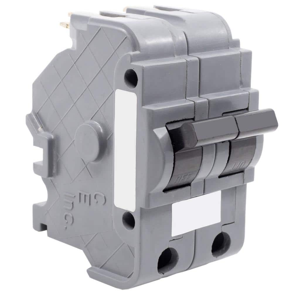
One thing I would double check is to make sure the breakers in positions 13,14 are not wired to anything else besides the contractor box. It doesn't look like it in your pictures, but looking close it looks like the wire that used to connect to the breaker in position 13 has been extended (wire nut next to that breaker) and now goes to a 15 amp breaker at the very bottom (#24).
I would not consider your first option (installing the GFCI device where the contactor is) without also replacing the breaker at 13/14 with a proper 2-pole breaker. Likely ~$30-40 additional.
Code requires a disconnecting means withing line-of-sight of any equipment. Having the timer up and around the corner from the pump may not meet that requirement (inspectors tend to vary as to what constitutes line of sight). But you could get around that by replacing what i assume is are direct-wired connections to the pump and swg, with a plug/socket under the deck appropriate to the voltage in use. (Whether you decide to switch to 120 or stick with 240). The requirement I think would also be met by installing a switch under the deck, perhaps in the existing box where the romex comes through from the basement. If you stick with 240V the switch needs to be 2-pole, switching both legs.
Otherwise I agree the location above the faucet at about eye level would be much better.
All the exterior wiring should to be in conduit, either EMT or PVC.
Last edited: