- Oct 25, 2015
- 5,814
- Pool Size
- 28000
- Surface
- Plaster
- Chlorine
- Salt Water Generator
- SWG Type
- CircuPool RJ-60 Plus
Folks,
I thought it might be helpful to put everything I learned about my recent install of a V-Green VS motor installation in one place.
I started out with a Jandy FHPM 1.0- 2 pump:

swapped the electric end for the square flange V-Greeen 1.65 motor:

And now I have my hybrid VS pump installed:

Here are the major things I learned that may help others doing this project:
Connections
Automation
One last thing. thanks to all @Jimrahbe ,@ajw22, @JamesW, @jimmythegreek and all the otherr experts that helped me get another huge upgrade completed.
Chris
I thought it might be helpful to put everything I learned about my recent install of a V-Green VS motor installation in one place.
I started out with a Jandy FHPM 1.0- 2 pump:
swapped the electric end for the square flange V-Greeen 1.65 motor:
And now I have my hybrid VS pump installed:
Here are the major things I learned that may help others doing this project:
Connections
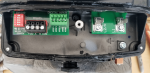
- Here's a look at the compartment:

- Notice the low voltage wires are on the left and HV is on the right. Use the left conduit hole for LV and the right one for HV. Figure out how to make the conduit connections work for this and be careful to select fittings that will allow you to get the bonding wire in place. It's VERY CLOSE (too close) to the conduit fitting. Make sure you check all this out carefully BEFORE you start pulling wire or you'll think you're done then have to disassemble and do it again.
- There's a divider in the cover that fits between the compartments. Don't have any wires that loop between compartments like this or they will keep the lid from closing and the divider will pinch the wire:

- Here's a photo of the cover and divider:

- Here's how to route the wires for proper installation with the cover almost in position. Notice divider just to the right of the hold down screw:

- The compartment has a history of leaking and filling up with water. There's a tiny o-ring that is supposed to seal the screw in the well on top of the cover. Use liberal amounts of silicone pool lube on the sealing surfaces around the edge and make sure they're clean. Here's the o-ring (see what I mean by tiny... too tiny?):

Automation
- I want to set the pump up to run just fast enough for the chlorinator as the base speed then use "step speeds" as they're called in the manual to increase for certain conditions:
- High speed anytime solar bypass is closed and flow has to make it to the roof.
- High speed anytime the gas heater is on
- I had no idea how I would access V-Green RS 485 from Pentair RS 485. So I put that aside for a potential future project.
- At first, I though to use relays to trigger the digital inputs from signals I'd pick up on the Pentair board. Fortunately I had a "learning moment" from Jim R about this. It was really dumb to do it this way when the controller is so eloquent. Sort of like advancing from the stone age to the bronze age. The digital inputs are designed to handle any signal 12-30 VAC or DC. so all I needed to do is run a signal from the gas valve on the heater and a signal from the solar valve input to the "step speeds". So set as follows:
- Step 1- duration 24 hrs, speed 1800 rpm
- Step 2-duration 0 hrs, speed 3200 rpm
- Step 3- duration 0 hrs, speed 3200 rpm
- To accomplish this I had to combine the common wires from the two signal wires. I was concerned about this and still haven't confirmed if its OK to do this from separate transformers like the pentair controller and the heater. But I convinced myself it was OK since the common connection from all were tied to the same ground. Luckily it worked fine and no problems with a week of operation. Here's how the connections look, a little fuzzy but far left "Step 1 has no connection. It runs anytime the digital inputs are not energized and the default is the internal timer which is set for 24 hrs Step 1 speed. Step 2 and 3 are the solar and gas heater connections respectively. Common signals (black) are twisted together:

- I'd much prefer screw terminals instead of the cheap spring type connectors but I guess this is part of keeping costs down. They do work fine and I've used these types of connectors outdoor for years with no problem so long as there's no water intrusion.
- The bonding connection and conduit connectors are a real pain. Be patient and get it right. It's worth the effort. I'm out of attachments so if you want to see what this looks like let me know and I'll PM it to you.
- Use the foam pad they give you to put under the motor between the motor and original saddle if there's a gap. Works great and literally no vibration
- Of course replace the seal in the pump when you do this.
- Look into type 1 and type 2 lightning/surge protection if this is a risk in your area. A couple hundred $ is well worth it.
One last thing. thanks to all @Jimrahbe ,@ajw22, @JamesW, @jimmythegreek and all the otherr experts that helped me get another huge upgrade completed.
Chris