Corey,I have four teenagers so I need to get them fed.
That is kind of like shoveling coal into an old steam engine.. It is a constant job..
Jim R.

Corey,I have four teenagers so I need to get them fed.
 www.troublefreepool.com
Here's the two screens I didn't post before.When you step through the menu, what cell type is shown?
And here is what you asked for.C,
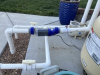
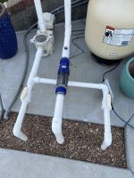
Can you show us a pic of the cell install itself, so that can see all the inputs and outputs, plumbing wise.
Thanks,
Jim R.
www.troublefreepool.com
You're telling me. 18, 17, 16, 15. Two boys, two girls. All but one over 6' and in constant sports, mainly competitive swim. My grocery bill is going to take a breath here in about four months when two of them leave the nest. Summer off school may put me into the poorhouse though.Corey,
That is kind of like shoveling coal into an old steam engine.. It is a constant job..
Jim R.
Thanks. I actually referred to your post in my initial research into SWG.Sorry for the delay gang. I've been on painting detail. Anyways, yes, the RJ module is factory configured at 240V, so you have to do the jumper thing to make it 120V. That's what I did. You can see my jumpers installed in my install link below.
Circupool RJ-45 Plus Install
This weekend I finally installed my RJ-45. I've been stalling on this for a long time, but the 2020 COVID-19 pandemic and resulting chlorine shortage finally pushed me over the edge. Plus, it was simply time. The Circupool Installation and Operation Guide is quite good, but here are some...
Can confirm, it is a T104 Timer.It appears you have a T104 timer - which is 240v - and the SWG appears to be wired to the timer correctly.
They are actually in the module. Mine came with two jumpers and I had to open the module to install them as you see in the pic. But my SWG is plugged directly into its own 120V outlet and I run my pump 24/7 so I have no separate timer.So are those jumpers in your timer box or inside the actual CircuPool control box?
Gotcha. Well, I am stumped on why mine isn’t working correctly. I guess tomorrow I’ll crack open the module and see where those jumpers are installed at on mine.They are actually in the module. Mine came with two jumpers and I had to open the module to install them as you see in the pic. But my SWG is plugged directly into its own 120V outlet and I run my pump 24/7 so I have no separate timer.
Timer was brand new. I bought it to run SWG since my Pentair pump is a VSP.Corey
Is that a new timer or was it installed before you got the SWG?
If it was there before, what's the estimated age?
Do NOT change any jumpers in the control module - at least not yet.
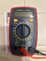
First order of business is to determine the voltage between timer terminals 1 and 3 - and between terminals 2 and 4.
If you don't have a multimeter or know how to use one, ask a neighbor or friend with one to check this for you.
Of course, the circuit breakers must be on and the ON/OFF switch in the timer must be on.
If the voltage between 1 and 3 - and between 2 and 4 equals around 240v, the SWG "should" work fine.
If the voltage only reads 120v between the abofe listed terminals, the SWG may need to be switched to 120v by installing the jumpers as shown in the manual.
BUT - before switching anything, report back here with the voltage readings.

No worries. The only thing I did different was mount it upside down but the manual told me to do that since I have a VSP that runs at like 1800rpm.Corey,
Thanks for the equipment system pics..
I was hoping to find something obviously stupid, the kind of thing I would do, but it all looks ok to me.
Jim R.
I just have it on all the time right now, as I'm running my pump 24/7 since I just opened it. I have not noticed the timer clock turning at all, but the silver on/off slider switch definitely supplies power to the SWG control box.Is your timer clock turning? On a T104, it needs to be wired for 240 volts to work.
Just an other indicator that the timer is wired to 120 volts. Confirm with your voltmeter.I have not noticed the timer clock turning at all
Timer off, Black on ground, red on 1 read 0. Black on ground, red on 3 read 123. Timer on, supplying power to control box, black on ground, red on 2 read 0, black on ground, red on 4 was 124. Sounds like my 240 timer is wired for 120.Corey
Is that a new timer or was it installed before you got the SWG?
If it was there before, what's the estimated age?
Do NOT change any jumpers in the control module - at least not yet.
First order of business is to determine the voltage between timer terminals 1 and 3 - and between terminals 2 and 4.
If you don't have a multimeter or know how to use one, ask a neighbor or friend with one to check this for you.
Of course, the circuit breakers must be on and the ON/OFF switch in the timer must be on.
If the voltage between 1 and 3 - and between 2 and 4 equals around 240v, the SWG "should" work fine.
If the voltage only reads 120v between the abofe listed terminals, the SWG may need to be switched to 120v by installing the jumpers as shown in the manual.
BUT - before switching anything, report back here with the voltage readings.
Timer off. Black on 1,, red on 3, reading 123.2vPut one probe on terminal 1 and one on terminal 3 - report voltage
Turn timer on
Put one probe on terminal 2 and one on terminal 4 - report voltage
If it reads 120v on those terminals - then it's wired for 120
If it reads 240v on those terminals - then it's wired for 240