SWG Wired Incorrectly?

WaynePool

Active member
Jul 6, 2020
42
Anaheim, California
Pool Size
15000
Surface
Plaster
Chlorine
Salt Water Generator
SWG Type
Pentair Intellichlor IC-40
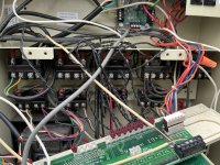
My SWG power is applied indicated by the lights whenever the filter pump has power. In the IntelliTouch i9+3 Center, there is the label on the Chlorinator Transformer (as shown Ihe attached picture): “The Chlorinator should only be powered on when the Filter Pump is ON”. So does “Filter Pump is ON” mean “running” or “power is applied”? If it means running then I need to reroute the power wires and hope someone can guide me through this.
 

Attachments

  • IMG_0664.jpeg
    IMG_0664.jpeg
    454.3 KB · Views: 22
  • IMG_0672.jpeg
    IMG_0672.jpeg
    332.5 KB · Views: 21
The SWG transformer should be powered by the LOAD screws on the filter pump relay.

The SWG should only be powered when the pump is running.
 
  • Like
Reactions: WaynePool
The SWG transformer should be powered by the LOAD screws on the filter pump relay.

The SWG should only be powered when the pump is running.
Thanks. Now I know why. There is no connector at the Filter Pump. Just wonder where do I buy that convector? See attached picture.IMG_0661.jpeg
 
The connector is attached to a relay.

Show us your relays.

You have any unused relay?
 

All of the newer relays used by Jandy, Hayward, Pentair are nominally 24v dc and are completely interchangeable. The one marketed for Hayward may be half the price of the ones from Pentair or Jandy.

The Omron brand was available at wholesale until the big three said they would pull their product if the wholesalers continued to offer them.

 
Wayne,

The Pump/Filter relay is 'normally' in the upper left relay position.. Find that relay and see if it is unused.

Show us a pic of where the SWCG transformer wires are connected to AC power...

Thanks,

Jim R.
 
Wayne,

Your left is not the same as my left.. :mrgreen:

The pump/filter relay is normally in the upper left of all the relays.

Follow the white and yellow wires from the SWCG transformer and see where they go...

Thanks,

Jim R.
 
Wayne,

Your left is not the same as my left.. :mrgreen:

The pump/filter relay is normally in the upper left of all the relays.

Follow the white and yellow wires from the SWCG transformer and see where they go...

Thanks,

Jim R.
They go to the circuit breaker of the filter pump.
 
Wayne,

As you have already pointed out that is wrong, and could cause the cell to explode.. It does not happen often, but it is possible.

Do you have any unused relays? Is the relay in the top left of your cabinet unused???

Thanks,

Jim R.
 

Enjoying this content?

Support TFP with a donation.

Give Support
Wayne,

As you have already pointed out that is wrong, and could cause the cell to explode.. It does not happen often, but it is possible.

Do you have any unused relays? Is the relay in the top left of your cabinet unused???

Thanks,

Jim R.
Yes , it is unused but there is no connector and wires at the filter pump control valve. So I must buy it somewhere
 
Wayne,

Is the relay missing, or is it there, and just not being used??

If the relay is there, it will have a small 2-wire cable going up into the electronics area. At the end of the small cable will be a connector.

Thanks,

Jim R.
 
  • Like
Reactions: WaynePool
Wayne,

Is the relay missing, or is it there, and just not being used??

If the relay is there, it will have a small 2-wire cable going up into the electronics area. At the end of the small cable will be a connector.

Thanks,

Jim R.
I will go out and take a closer look tomorrow morning. I know it was used before because there still has the two lines in but no wire on the load lines
 
Wayne,

Is the relay missing, or is it there, and just not being used??

If the relay is there, it will have a small 2-wire cable going up into the electronics area. At the end of the small cable will be a connector.

Thanks,

Jim R.
Here is the drawing I traced the wires this morning.
 

Attachments

  • IMG_0684.jpeg
    IMG_0684.jpeg
    345.4 KB · Views: 20
  • IMG_0678.jpeg
    IMG_0678.jpeg
    531 KB · Views: 23
  • IMG_0679.jpeg
    IMG_0679.jpeg
    441.6 KB · Views: 19
  • IMG_0680.jpeg
    IMG_0680.jpeg
    581.2 KB · Views: 20
Wayne,

To fix your SWCG power issue, you will need to do the following..

Just to make sure..... Might want to confirm that your SWCG transformer is currently connected to 240.. If it is, the Violet and Black SWCG transformer wires will be connected together with a wire nut. And the Yellow wire and White wire are currently connected to L1 and L2 on a 240 volt breaker... If true continue on..

1. Move the Yellow/Green cable from the Pump/Filter relay, and install it on your Aux 1 relay. Green to Line1 and Yellow to Load 1. (Just like it is now..)

2. Remove the coil wire for the Aux 1 from the Elect. Heat port, and move it to the Pump/Filter port.

3. Remove the Aux 1 coil wire from the Aux 1 port, and move it to the Electric heat port.

4. Remove the Yellow and White SWCG transformer wires from the Breaker and install them on the Load 1 and Load 2 pins of the Pump/Filter relay. (Does not matter which color goes where.)

5. Run wires from the Circuit Breaker and connect 240 volts to Line 1 and Line 2 of the pump filter relay.

Now, the SWCG will only get power when the pump/filter relay is closed..

Your heater will work from the Aux 1 relay, but you will never be able to tell the difference.

Obviously, you are doing all of this with the power to the EasyTouch shut off.

Thanks,

Jim R.
 
Last edited:
  • Like
Reactions: WaynePool
Jim,
I am very impressed with your suggestion and step by step instructions to fix my SWG power issues. It’s amazing you are able to thoroughly do that just based on my hand drawing and couple pictures i attached in this post.it’s very clear what I need to do.
Before I start it either tomorrow or later in the week, I want to learn how to remove a small 2-pin male connector from its female connector at the port. I have tried to pull it up but with no sucess; so I just wonder if there is a tab lock I need to press in or out, or just pull straight up harder.
Looking back on these incorrect wiring connection, what’s a mess the pool guy had done when he replaced my filter pump 3 years ago. In addition to the cost of the Pentair VSF pump and installation labor, he charged me an extra $100 for replacement the filter pump circuit breaker + swap location with a circuit breaker if other pump + rewire the wiring. I asked him the power circuit breaker working before so why needed to rewiring then; his answer was it might work before but it was incorrect wiring. Well, what can I say? However, I give him a reasonable of doubt by saying he might thought he knew how to correctly rewiring the SWG powercircuit..

Thanks

Wayne
 
Wayne,

It has been some time since I removed or connected my aux relay connectors.. I thought it was just a simple pull it up, but now that you bring it up, I am not sure..

Tomorrow morning, I'll go out to my EasyTouch and see for myself..

I'll let you know what I find...

In the meantime, let's see if Tom has any ideas... Calling @ogdento

Thanks,

Jim R.
 
Pull up harder.

There is the tab on the connector that I circled in blue.

It snaps in under the ears on the socket that have green dots on them.

You need to pull up hard enough and wiggle the socket a bit to have the ears flex out and release the socket.

1708920695789.png
 
  • Like
Reactions: ogdento

Enjoying this content?

Support TFP with a donation.

Give Support
Thread Status
Hello , This thread has been inactive for over 60 days. New postings here are unlikely to be seen or responded to by other members. For better visibility, consider Starting A New Thread.