
Stinging sensation – bonding issue, stray voltage, or something else?
- Thread starter newtoPoolsSWG
- Start date
You are using an out of date browser. It may not display this or other websites correctly.
You should upgrade or use an alternative browser.
You should upgrade or use an alternative browser.
Doh sorry… so not getting any AC amps now or mA. So I flipped to volts and it dropped quite a bit. Perhaps community demand is down now too.You have it set to DC.
Switch to AC amps.

Attachments
- May 3, 2007
- 18,095
- Pool Size
- 20000
- Surface
- Plaster
- Chlorine
- Salt Water Generator
- SWG Type
- Hayward Aqua Rite (T-15)
The real issue here is a problem with the bonding. NEV just revealed the issue. As I mentioned before, it is hard to get the power company involved when NEV is only a few volts.
Also, note that NEV is highly variable and is dependent on the time variant loading of each phase. Dynamic loading shifting can also cause a time varying phase shift in NEV so the frequency may not be exactly 60 Hz. Also, the NEV waveform is not a perfect sine-wave so that can influence the frequency measurement as well due to the harmonics. A 10% shift would not be surprising.
Also, it wouldn't surprise me if you saw a higher NEV during week than the weekends. Industrial loading is usually higher during the week and residential loading is usually lower during the week (when not in covid lockdown) which would cause more phase imbalance.
Many builders use a loop of bond wire, which is insufficient for bonding the deck properly.
In my opinion, all decks need a 3' rebar or wire mesh grid for proper bonding.
In my opinion, all decks need a 3' rebar or wire mesh grid for proper bonding.
Last edited:
The measurements are being done at points close to each other, so the voltage will tend to equalize and you can’t say that it is only 1 or 2 volts.
You need to try to get to a zero ground reference point, which would be difficult or impossible to do as the NEV tends to go everywhere.
It might be a hot wire in the ground somewhere and the current is going through the ground until it gets to the pool bonding grid and the house main grounding electrode and then it travels back to the transformer on the utility neutral.
It might be a bad neutral causing the unbalanced current to dump into the ground via the grounding electrode and the bonding grid.
It might be that the neighbor has a bad neutral and they are dumping current into the ground via their main grounding electrode and the current is being picked up by the pool bonding grid and the house grounding electrode and returning to the utility neutral.
In that case, even a relatively good bonding grid will show some voltage differences at different points due to current flowing through different paths with different amounts of resistance.
The pool bonding grid is effectively a giant grounding electrode and it is connected to the grounding system in multiple places wherever the equipment is bonded and grounded such as at a light niche, pump motor casing/frame, subpanel etc.
Current can travel through all equipment grounding conductors to the main panel where the EGCs connect to the neutral bus bar.
The bonding grid, the main electrode and the ground itself will tend to equalize all voltage in the ground and it will attract any stray current and direct it to the utility neutral.
This can be tested by disconnecting the main neutral at the meter and checking for voltage between the main neutral and the panel neutral lug.
You can also measure for current flowing on the neutral while it is connected.


 www.nfpa.org
https://www.ecmweb.com/basics/bondi...ng-truth-about-grounding-electrode-conductors
You need to try to get to a zero ground reference point, which would be difficult or impossible to do as the NEV tends to go everywhere.
It might be a hot wire in the ground somewhere and the current is going through the ground until it gets to the pool bonding grid and the house main grounding electrode and then it travels back to the transformer on the utility neutral.
It might be a bad neutral causing the unbalanced current to dump into the ground via the grounding electrode and the bonding grid.
It might be that the neighbor has a bad neutral and they are dumping current into the ground via their main grounding electrode and the current is being picked up by the pool bonding grid and the house grounding electrode and returning to the utility neutral.
In that case, even a relatively good bonding grid will show some voltage differences at different points due to current flowing through different paths with different amounts of resistance.
The pool bonding grid is effectively a giant grounding electrode and it is connected to the grounding system in multiple places wherever the equipment is bonded and grounded such as at a light niche, pump motor casing/frame, subpanel etc.
Current can travel through all equipment grounding conductors to the main panel where the EGCs connect to the neutral bus bar.
The bonding grid, the main electrode and the ground itself will tend to equalize all voltage in the ground and it will attract any stray current and direct it to the utility neutral.
This can be tested by disconnecting the main neutral at the meter and checking for voltage between the main neutral and the panel neutral lug.
You can also measure for current flowing on the neutral while it is connected.
8 Items that Form the Grounding Electrode System | NFPA
Eight items that form the grounding electrode system
Have you done any service work lately, and noticed a spark as you connect or reconnect the grounding electrode conductor to the ground rod of what appeared to be a perfectly normal electric service?
Have you ever disconnected the grounding electrode conductor at a water pipe and received a shock?
Have you ever noticed any arcing or sparking at a loose grounding electrode conductor at an outbuilding that has a connection to its own separate ground rod?
If you answered “yes” to any of these questions, the culprit is more than likely currents in the grounding electrode conductor.
The case of the open neutral.
In a properly functioning electrical system, the neutral conductor carries the imbalance current of the system.
For a single-phase system, the imbalance is the difference between the currents in the two “hot” legs of the transformer.
The current imbalance needs to return via the neutral conductor back to the transformer.
But, if that neutral is open, the imbalance current will seek other paths to get back to the neutral leg of the transformer.
At the main service, the neutral and ground are connected via the main bonding jumper.
If the ground path has a low enough resistance, it may prove to be a satisfactory return path, and the imbalance current will travel through the main bonding jumper into the grounding electrode.
Since the transformer neutral is grounded by the utility, and since the main bonding jumper connects the neutral and grounding conductor at the service, as per NEC requirements, the ground path provides a complete return for the imbalance current.
Even though the building you're working on may have a completely continuous neutral back to the transformer, the house next door or a building somewhere in the general vicinity may have an open neutral.
If the building you're working in and the building with an open neutral have some type of conductive path between them, current may return via that path.
A metal water pipe is a good example of such a connection.
Current can come “up” through a ground rod or a water pipe into the building you're working on, due to an open neutral in a neighboring building.
Is the current coming or going?
So now you're convinced that there can be current flowing in a grounding electrode conductor.
Next time you're on-the-job, use your ammeter to measure the current in the grounding electric conductor before you open up that connection.
If you measure a current, how do you know if it's due to current going “down” into the ground at this building or current coming up through the grounding electrode conductor in your building and returning back to the source via your neutral?
Unfortunately, putting an ammeter on the conductor will only prove that there is current flowing in the conductor.
It does not tell you the direction of that current.
You must use Kirchoff's Law to determine the direction of the current flow.
Kirchoff's Law states that all currents entering a connection are equal to the currents leaving a connection.
Simply put, all currents must balance.
Example No. 1. You're working on a single-phase, 120/240V service.
You measure 11A in the black conductor at the main service panel.
You measure 5A in the red conductor at the main service panel.
On a single-phase service, the neutral current is the difference between the two legs of the transformer, which in this case is 6A.
Therefore, if you measure 6A in the grounding electrode conductor and 0A in the neutral service entrance conductor, you can be relatively certain that the neutral is open, and your building is dumping current into an alternate return path (i.e. the grounding electrode).
Example No. 2. You're working on a single-phase, 120/240V service.
You measure 11A in the black conductor at the main service panel.
You measure 5A in the red conductor at the main service panel.
As in the first example, the neutral current will be the difference between the two legs of the transformer, which is 6A.
However, this time you measure 8A in the grounding electrode conductor.
How can this be?
Can there possibly be more current being dumped into the ground by the system you're working on than the system imbalance current?
Are there 2A of extra phantom current?
When you measure the current in the neutral, you find 14A.
Now you're really confused.
Applying Kirchoff's Law to the circuit, you quickly realize that the 6A of current imbalance from the system you're working on is being joined with 8A coming into this system from somewhere else.
https://www.ecmweb.com/basics/bondi...ng-truth-about-grounding-electrode-conductors
Last edited:
@JamesW and @mas985
I can't say thanks enough for the continued engagement as this is consuming us, but this is the only way we can try to tackle the issue.
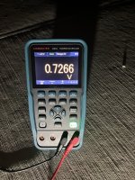
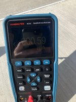
I repeated the mA test this morning curious if it changed, and it did. Pic 1 - shows 0.59 mA while the pump was running. Pic 2 - shows 0.27 mA after I shut the pump off. The reading was steady, to me, it seems to suggest the pump is contributing here?
I watched nearly all of the Mike Holt video on testing NEV. I'm going to explain what I did and show you pictures... which I think actually helps me understand the problem... and flips what I suspected.
NEVsetup2 - NEV setup (screwdriver in ground 6-8' from meter connected to wire)
NEVMeterRead - reading on the meter
NEV-HeatPumpBond - reading on bond nut of heat pump
NEV-PoolWater - reading in water
Not shown, the handrail and ladder read the same as the pool/bond wire points - right around 1v.
Also not pictured, the point where I keep getting the higher voltage 1.2v and the .59 mA in Pic 1, is a bolt on the slide... the NEV read was in line or a little less than the meter read.
This seems to indicate something connected to the bond wire is not actually grounded.
I can't say thanks enough for the continued engagement as this is consuming us, but this is the only way we can try to tackle the issue.
I repeated the mA test this morning curious if it changed, and it did. Pic 1 - shows 0.59 mA while the pump was running. Pic 2 - shows 0.27 mA after I shut the pump off. The reading was steady, to me, it seems to suggest the pump is contributing here?
I watched nearly all of the Mike Holt video on testing NEV. I'm going to explain what I did and show you pictures... which I think actually helps me understand the problem... and flips what I suspected.
NEVsetup2 - NEV setup (screwdriver in ground 6-8' from meter connected to wire)
NEVMeterRead - reading on the meter
NEV-HeatPumpBond - reading on bond nut of heat pump
NEV-PoolWater - reading in water
Not shown, the handrail and ladder read the same as the pool/bond wire points - right around 1v.
Also not pictured, the point where I keep getting the higher voltage 1.2v and the .59 mA in Pic 1, is a bolt on the slide... the NEV read was in line or a little less than the meter read.
This seems to indicate something connected to the bond wire is not actually grounded.
Attachments


At this point, I would have an electrician check for current on the neutral to see if that is an issue.
So the average electrician could conduct that test correct? What happens if that is positive? Is that a power company issue?At this point, I would have an electrician check for current on the neutral to see if that is an issue.
I would want a really good electrician.So the average electrician could conduct that test correct?
An average electrician will be mostly clueless and useless.
If the neutral is dumping current into the ground, it means that your neutral is probably bad and the power company should be responsible.What happens if that is positive?
If the neutral is carrying excessive current that is being picked up from the ground, it might be due to a bad neutral at a neighbor’s house or maybe a hot line in the ground somewhere.
The power company can check the neighbor’s neutrals.
If those check out ok, then they can look for a hot line in the ground leaking current.
Probably, but an open hot line can come from other sources.Is that a power company issue?
For things like this, the power company tends to do the minimum amount necessary to clear the call.
They might do some cursory tests and declare everything to be “within specifications”, whatever that means.
Typically, you need to be very persistent to get any real action from them.

In my opinion, small voltage differences do not necessarily mean that the bonding grid is defective.The real issue here is a problem with the bonding.
If you have current flowing, there will always be voltage differences from different points even if you have a near perfect bonding grid.
If current was not flowing, the voltage would equalize.
- May 3, 2007
- 18,095
- Pool Size
- 20000
- Surface
- Plaster
- Chlorine
- Salt Water Generator
- SWG Type
- Hayward Aqua Rite (T-15)
I disagree. A well bonded grid (i.e. low resistance), connected to ground, with all the elements properly connected should have no difference in voltage. The only way to get a voltage difference along a conductor is when there are very high currents flowing and the wire has a high resistance (i.e. Vd = IR). This is exactly what causes NEV. However, this should not be the case with a proper bonding grid around a pool.In my opinion, small voltage differences do not necessarily mean that the bonding grid is defective.
If you have current flowing, there will always be voltage differences from different points even if you have a near perfect bonding grid.
If current was not flowing, the voltage would equalize.
They’re not testing between different points directly on the bonding grid.
They’re testing from a bonded point to an unbonded point.
If the deck only has a loop of bond wire, the test point on the deck and the bond wire have a lot of concrete separating the test point and the bond wire.
Concrete has poor conductivity.
You can have current being picked up on the bonding grid and that current will flow to the utility neutral.
If the deck had a copper mesh going out 3 feet, that would likely eliminate the difference.
In any case, the bonding grid is insufficient even though it might be code compliant.
It might be a defective or missing bonding grid or there might be a lot of current flowing, which can create potential/voltage differences even with a code compliant bonding grid.
Even a wire has a voltage difference if there is current flowing.
You measure from two points on a wire and you get a voltage difference even though the wire is as perfectly bonded as it can get.
We have no idea how much current is flowing through the property.
Maybe it's 1 amp and maybe it's 10 amps, or more.

You measure from two points on a wire and you get a voltage difference even though the wire is as perfectly bonded as it can get.
We have no idea how much current is flowing through the property.
Maybe it's 1 amp and maybe it's 10 amps, or more.
If you’re testing to the water, the water is only bonded at a few spots and the water has resistance, which will create a voltage difference between the water test point and the bonding grid.
Maybe a better bonding grid would help reduce or eliminate the problem, but I don’t think that at this point we can say that the entire problem is only the result of a defective bonding grid.
If there is a source of excessive stray voltage/current, it will be difficult or impossible to create a bonding grid that is good enough to eliminate all voltage differences.
You would need to create a giant copper or silver grid to form a Faraday cage that completely surrounds the entire pool area and it picks up all current and routes it around the pool area.
Last edited:
- May 3, 2007
- 18,095
- Pool Size
- 20000
- Surface
- Plaster
- Chlorine
- Salt Water Generator
- SWG Type
- Hayward Aqua Rite (T-15)
What would be placing a 120v on a bonding grid that is connected to a ground that would not trip a breaker? That is not a realistic scenario. The more realistic scenario is NEV with a poorly bonded deck.
- May 3, 2007
- 18,095
- Pool Size
- 20000
- Surface
- Plaster
- Chlorine
- Salt Water Generator
- SWG Type
- Hayward Aqua Rite (T-15)
It should not be that hard. Yes, concrete is a poor conductor but if the rebar is in the middle of the concrete (between the surface and the earth) and is properly bonded, the concrete surface should be close to the same voltage as the bonding wire.If there is a source of excessive stray voltage/current, it will be difficult or impossible to create a bonding grid that is good enough to eliminate all voltage differences.
Maybe the utility wires are exposed underground.What would be placing a 120v on a bonding grid that is connected to a ground that would not trip a breaker?
Maybe the neighbor has a bad neutral and they are sending 10 to 20 amps into the ground.
That current can be picked up by the pool bonding grid where it will flow to the main neutral.
The current will go through the house neutral, which does not go through a breaker.
In any case, you can measure for current on the neutral.
If the main breakers are on, you can test the current on both hot legs and the neutral should carry the difference.
For example, if the red is 28 amps and the black is 43 amps, the neutral should show 15 amps.
If it’s less, then the neutral is bad.
If it’s more, the bonding grid and the grounding electrode are picking up extra current from the ground from some unknown source.
If the main breaker is off, the neutral should show zero amps as there will be no unbalanced current.
An electrician can also disconnect the neutral at the meter to isolate it from the house and check for voltage between the neutral and the house.

Last edited:
Yes, concrete is a poor conductor but if the rebar is in the middle of the concrete (between the surface and the earth) and is properly bonded, the concrete surface should be close to the same voltage as the bonding wire.
As far as I recall, I’m not sure there was any mesh or rebar added which I would imagine makes the bonding more effective.
Possibly no mesh or rebar, which is allowed by code as long as there is a bonding ring.
At issue was code language in Sec. 680.26(B)(2), relating to equipotential bonding around the decks of many in-ground pools. In 2007, during the final months of the 2008 NEC revision cycle, wording in the 2005 Code that mandated an equipotential copper wire mesh grid to suppress stray voltage around pools built without traditional concrete/rebar decks was supplemented with an alternate means. Language specifying a new, alternate method of bonding — a single No. 8 solid wire installed around the perimeter of such pools — was inserted.
No sooner was the ink dry on the 2008 NEC than critics of the reversal began mobilizing. A loose affiliation of parties that had voiced concern about the adequacy of the single wire as a means of preventing shocks and how the change was made soon coalesced, embarking on an ultimately fruitless three-year battle to restore the 2005 wording. Their efforts hit a dead end in August, however. When the National Fire Protection Association’s (NFPA) Standards Council voted to deny an appeal of an NEC Code Making Panel’s near-unanimous recommendation to retain the 2008 single-wire provision — overriding support for the 2005 wording expressed by other NFPA bodies — grid backers had lost.
https://www.ecmweb.com/construction/article/20888578/a-debate-in-the-deep-end
Mike Holt has a video where he drops a live wire into a pool and 10.35 amps were flowing into the water without tripping a breaker.What would be placing a 120v on a bonding grid that is connected to a ground that would not trip a breaker?
The current traveled through the water to the bonding grid and then to the house main neutral and into the earth.
He tested the voltage differential at several places and found substantial differences as you would expect as the hot is at 120 volts and the neutral is at about zero.
So, it can definitely happen without tripping a breaker.
Most breakers are 15 amps or more, so you can have up to 15 amps on a 15 amp breaker without tripping the breaker.
He changed the video to private, so it’s not available any more.
It was his “How to test a pool bonding grid” video.
Below is a picture of his ammeter on the live wire that he dropped in the pool.

Thread Status
Hello , This thread has been inactive for over 60 days. New postings here are unlikely to be seen or responded to by other members. For better visibility, consider Starting A New Thread.